Electric vacuum cleaner

A vacuum cleaner, electric technology, applied in the direction of vacuum cleaners, suction filters, cleaning equipment, etc., can solve the problems of blockage of filter surface, difficulty in forming a tight state of dust collection chamber, low dust collection power, etc., to achieve the effect of maintaining dust collection power

Inactive Publication Date: 2013-10-02
PANASONIC CORP
View PDF1 Cites 0 Cited by
  • Summary
  • Abstract
  • Description
  • Claims
  • Application Information

AI Technical Summary

Problems solved by technology

[0003] However, the dust separated by the cyclone dust collecting part after the conventional dust collection is affected by the swirling airflow in the cyclone dust collecting part and accumulates in the electric vacuum cleaner below the dust collecting part. Dust floats up and clogs the filter surface, so there is a problem of low suction power
[0004] In addition, due to the natural accumulation of dust under the influence of the swirling airflow in the swirl dust collection part, it is difficult to form a compact state in the dust collection chamber, and it is necessary to frequently collect dust to form a full state with less than the capacity of the dust collection chamber. expel dust

Method used


Image

  • Electric vacuum cleaner
  • Electric vacuum cleaner
  • Electric vacuum cleaner

Examples


Embodiment approach 1

[0025] Hereinafter, embodiments of the present invention will be described with reference to the drawings. In addition, the present invention is not limited by this embodiment.

[0026] use Figure 1A ~ Figure 6B , the electric vacuum cleaner in Embodiment 1 of the present invention will be described.

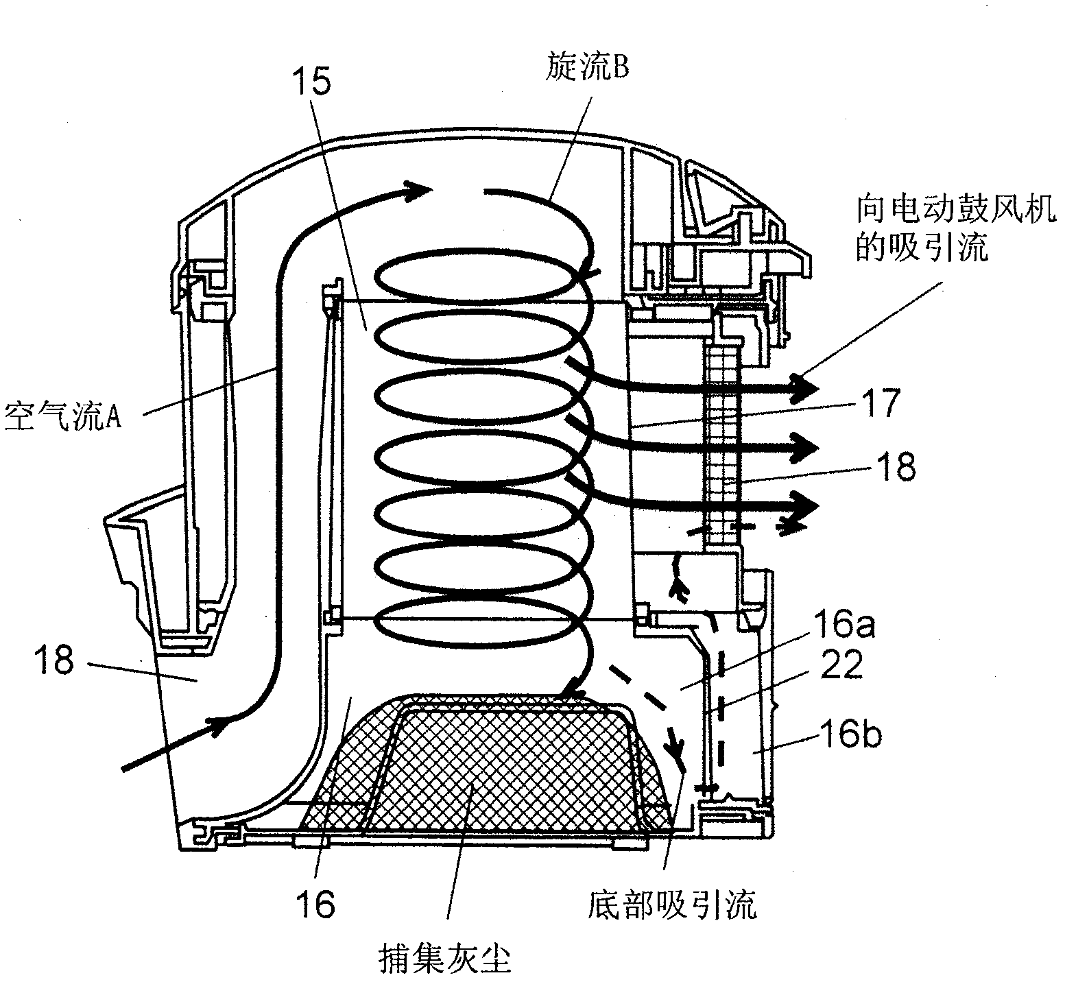
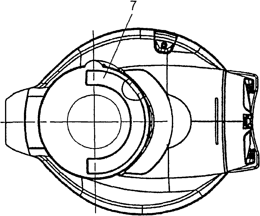
[0027] Figure 1A , Figure 1B It is a plan view and a side view of the electric vacuum cleaner main body in Embodiment 1. figure 2 It is a central sectional view of the electric vacuum cleaner main body in Embodiment 1. Figure 3A , Figure 3B It is a central sectional view and detailed views of each part of the dust box which is the characteristic of the present invention. Figure 4 is the plan view of the swirl chamber. Figure 5A , Figure 5B It is a schematic sectional view of the dust box and a sectional view of the dust chamber viewed from the direction of the motor. Figure 6A , Figure 6B It is a cross-sectional view and a plan view showing a structure in whi...

Embodiment approach 2

[0043] Hereinafter, embodiments of the present invention will be described with reference to the drawings. In addition, this invention is not limited to this embodiment.

[0044] use Figure 7A ~ Figure 9 , the electric vacuum cleaner according to Embodiment 2 of the present invention will be described.

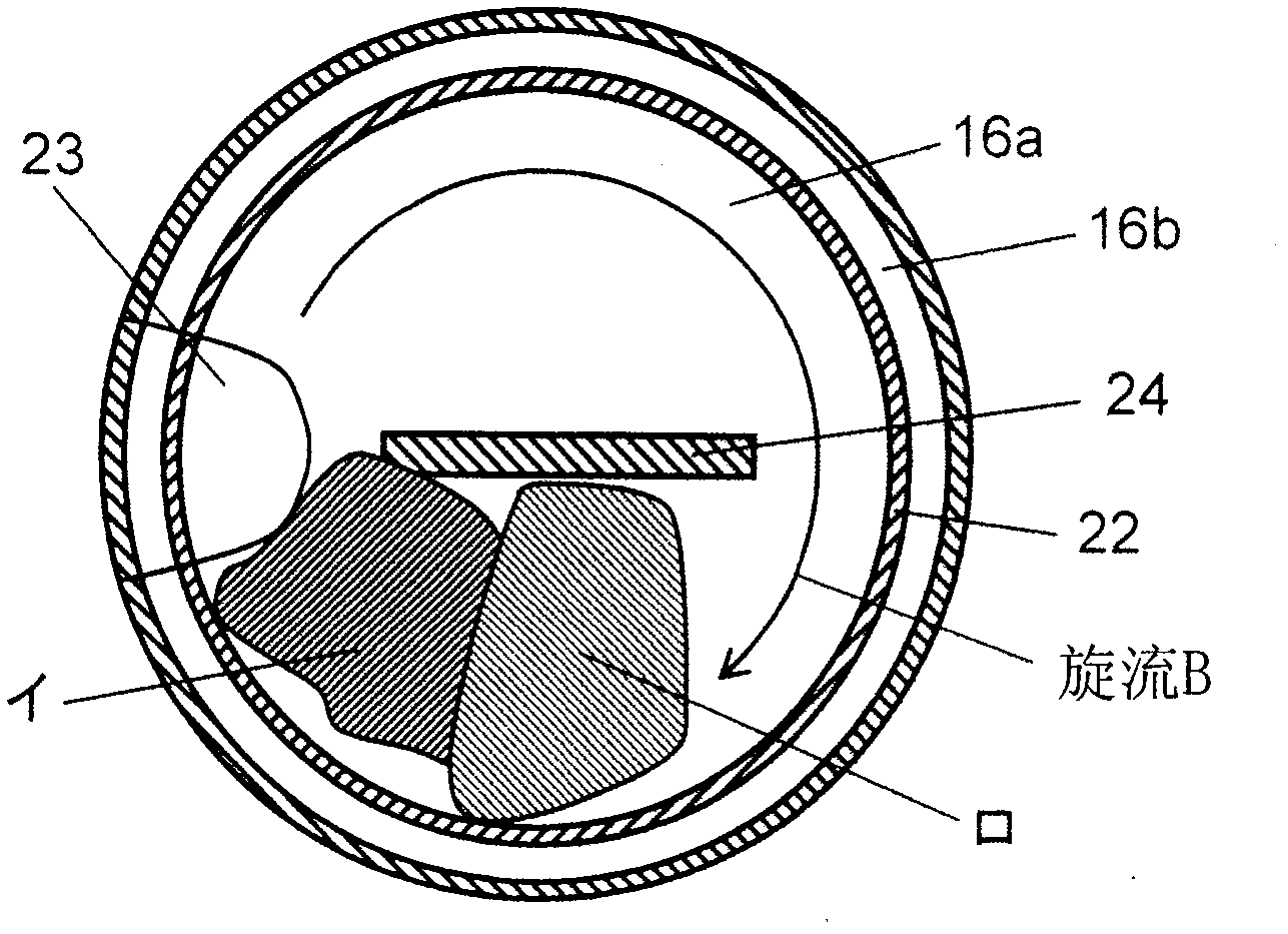
[0045] Figure 7A , Figure 7BIt is a central sectional view and partial detailed view of the dust box in Embodiment 2. Figure 8 It is a perspective view of main parts when the bottom cover is opened in the dust box in Embodiment 2. Figure 9 It is a schematic diagram showing the structure that collects dust in the dust box. In addition, the same symbols as in Embodiment 1 have the same structure, and description thereof will be omitted.

[0046] In Embodiment 2, the lower end portion of the separation wall 22 is divided into two separation walls to form a double wall, the inner side is a comb-shaped separation wall 20 that forms a comb-like concavo-convex, and the out...


PUM


Abstract

A dust collection box of the invention is composed of a separation part, a dust collection part which collects the dust separated in the separation part, and a bottom cover which covers the lower opening of the dust collection part, wherein, the separation part is provided with a swirling chamber which is configured to the upstream side of an electric air blower which generates the sucked air current and is composed of a filtering net that is provided with a plurality of small through holes, and a crease type filter which covers the periphery. Through the suction of a communication hole whichis formed between the lower part of a separation wall of the dust collection part and the bottom cover, the floating of the dust which is caught in a first dust collection chamber in the swirling chamber can be prevented, and the dust suction force can be sustained.

Description

technical field [0001] The present invention relates to an electric vacuum cleaner having a structure of a cyclone dust collecting unit that rotates sucking in air to separate and accumulate dust by centrifugal force, and has a detachable dust box. Background technique [0002] In conventional electric vacuum cleaners having a cyclone dust collecting part, generally, the dust separated by the cyclone dust collecting part after dust collection is affected by the swirling airflow in the cyclone dust collecting part and accumulates under the dust collecting part. side (for example, refer to Patent Document 1). [0003] However, the dust separated by the cyclone dust collecting part after the conventional dust collection is affected by the swirling airflow in the cyclone dust collecting part and accumulates in the electric vacuum cleaner below the dust collecting part. Dust floats up and clogs the filter surface, resulting in a problem of low suction power. [0004] In additio...

Claims


Application Information

Patent Timeline
Patent Type & Authority Patents(China)
IPC IPC(8): A47L5/22A47L9/16
Inventor 雁瀬伸幸奥岛雅史岩佐彻仲本博司
Owner PANASONIC CORP
Why Eureka
Try Eureka