Movable oiling cup and oiling method

An oil filling cup and movable technology, which is applied in the direction of rail brakes, engine components, lubricating oil containers, etc., can solve the problem of increasing oil plugs, oil nozzles, blank weight drilling and tapping processes, the feasibility is not large, and the deceleration top cannot be modified and other problems, to achieve the effect of reasonable location, saving processing cost and saving rough cost

Inactive Publication Date: 2011-06-29
HARBIN DONGAN HYDRAULIC MACHINERY
View PDF0 Cites 0 Cited by
  • Summary
  • Abstract
  • Description
  • Claims
  • Application Information

AI Technical Summary

Problems solved by technology

The casting molds of more than 30 kinds of shells have to be scrapped, and the oil plugs, oil nozzles, blank weight, drilling and tapping processes have been added, and the retarder in use cannot be modified, so the feasibility is not great

Method used


Image

  • Movable oiling cup and oiling method
  • Movable oiling cup and oiling method
  • Movable oiling cup and oiling method

Examples


Embodiment 1

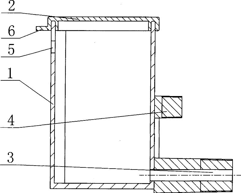
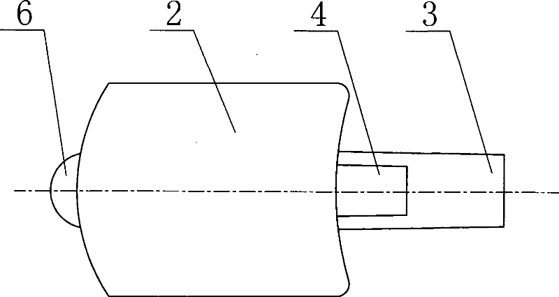
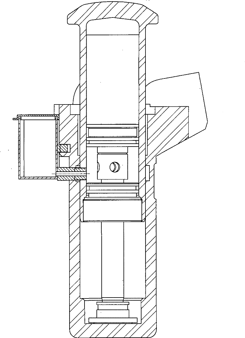
[0021] Movable oil filling cup, its composition includes: a cup body 1, the cup body is connected to the cup cover 2, the cup body is connected to the oil pipe 3 and the fixed column 4, and the oil pipe and the fixed column are inserted into the deceleration top shell In the corresponding hole above, the oil cup has ventilation holes 5. The connection between the shell and the cup is bonded by adding glue to the connection between the oil pipe and the fixed column and the shell. The contact surface of this product and the shell is matched in a large arc shape. Tubular shape. By designing a reasonable wall thickness of the oil cup body, it can be strong and damage-resistant. The most commonly used wall thickness is 1.5-3 mm. The wall thickness of this product can be selected as 2 mm. Referring to the structure of the expansion bolt, the oil pipe and the fixing column are designed with threaded grooves, which are in interference fit with the casing to ensure a tight connection...

Embodiment 2

[0023] As for the movable oil filling cup, the cup cover has a protective edge 6 . In order to ensure the tightness of the seal, an embedded groove edge is designed. The sealing method of the cup body and the cup cover is borrowed from foreign methods, and the groove seal is adopted, and an outward draft angle of 5° is added in the 4mm range of the upper mouth of the cup body.

[0024] This product works outdoors, and the working environment is very harsh, with dust, rain, and snow, and the oil in the oil cup must not be corroded. Therefore, the oil cup should have a dust-proof cover to ensure that the oil does not mix with other substances.

[0025] In order to ensure the fluidity of the grease in various seasons, a special lubricating grease is designed through experiments. It is used in conjunction with No. 10 aviation lubricating oil and No. 3 lithium base grease at a ratio of 1:1.

[0026] The oil cylinder moves at high speed in the shell, and the friction generates a l...

Embodiment 3

[0028] The oiling method of the movable oiling cup is to insert the oil pipe connected to the cup body and the fixed column into the corresponding hole on the deceleration top shell. When the oil cylinder reciprocates in the inner cavity of the shell, internal pressure is formed, and the oil in the oil cup is sucked into the storage tank. In the oil tank, ventilation holes are left on the cup body to make the oil flow smoothly.


PUM


Abstract

The invention discloses a movable oiling cup and an oiling method. The prior retarders adopt a structure that a casting oil cup is added on a shell, but the retarders being used cannot be improved, so the feasibility of the structure is not good. The movable oiling up comprises a cup body (1). The cup body is correspondingly connected with a cup cover (2). The cup body is connected with an oil pipe (3) and a fixed column (4). The oil pipe and the fixed column are inserted into corresponding holes on the shell of the retarder. The oil cup has a vent (5). The product is used as a lubrication device for the shell of the retarder in the gravity shunting of the marshalling stations.

Description

Technical field: [0001] The invention relates to a lubricating device for a deceleration top casing on a hump shunting station of a railway marshalling station, in particular to a movable oiling cup and an oiling method. Background technique: [0002] The deceleration jack is a hydraulic braking device used on the hump shunting of the railway marshalling station. The housing assembly is installed on the track, and the oil cylinder assembly performs reciprocating and rotating motions on the housing assembly. Vehicles run frequently every day, up to thousands of times a day, and have high requirements for lubrication. And the lubricating grease reserves in the original oil storage tank in the housing is seldom, often occurs that lubrication is bad, causes dry grinding phenomenon. This will cause the oil cylinder to fail to return in time, or even fail to return in a long time, and cannot play the role of braking, which will cause potential safety hazards for the vehicle. The...

Claims


Application Information

Patent Timeline
Patent Type & Authority Patents(China)
IPC IPC(8): B61K7/02F16N19/00
Inventor 邱洪涛孔令军宁士才
Owner HARBIN DONGAN HYDRAULIC MACHINERY
Why Eureka
Try Eureka