
Vertical reinforced concrete component-connection node of buckling-restrained brace

A technology for connecting nodes and buckling constraints, applied in building structures, buildings, etc., can solve problems such as perforation of shaped steel, difficulty in arranging stirrups and longitudinal bars, and difficulty in connecting nodes with steel supports, so as to save steel consumption and simplify construction. process, the effect of improving the bearing capacity

Active Publication Date: 2010-03-17
TONGJI UNIV ARCHITECTURAL DESIGN INST GRP CO LTD
View PDF0 Cites 32 Cited by
  • Summary
  • Abstract
  • Description
  • Claims
  • Application Information

AI Technical Summary

Problems solved by technology

The invention solves the problem of difficulty in arranging steel support connection nodes in the concrete frame, and at the same time solves the problems that the section steel needs to be perforated and the stirrups and longitudinal bars are difficult to arrange due to the section steel embedded in the concrete member

Method used


Image

  • Vertical reinforced concrete component-connection node of buckling-restrained brace
  • Vertical reinforced concrete component-connection node of buckling-restrained brace
  • Vertical reinforced concrete component-connection node of buckling-restrained brace

Examples


Embodiment Construction

[0031] The present invention is further illustrated below by means of embodiments in conjunction with the accompanying drawings.

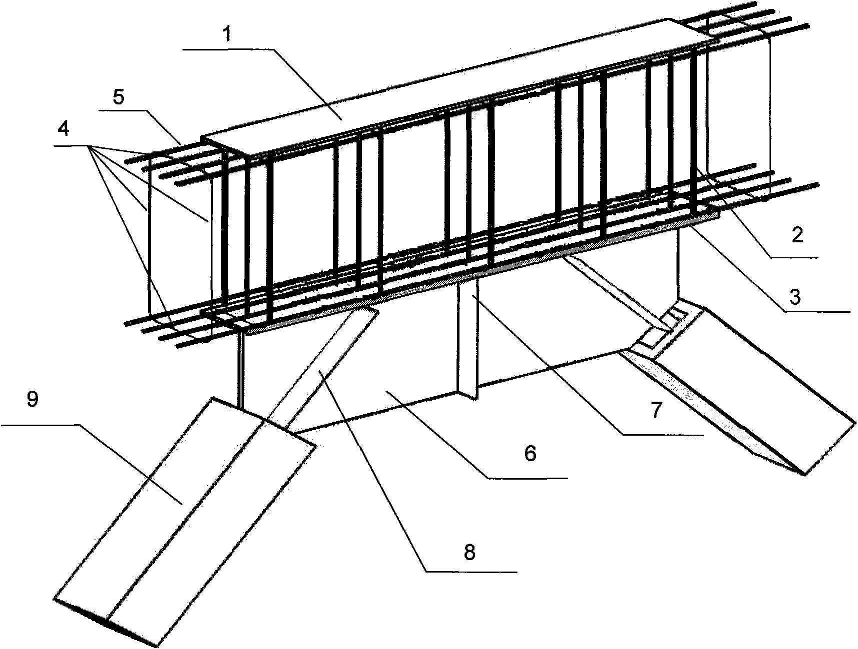
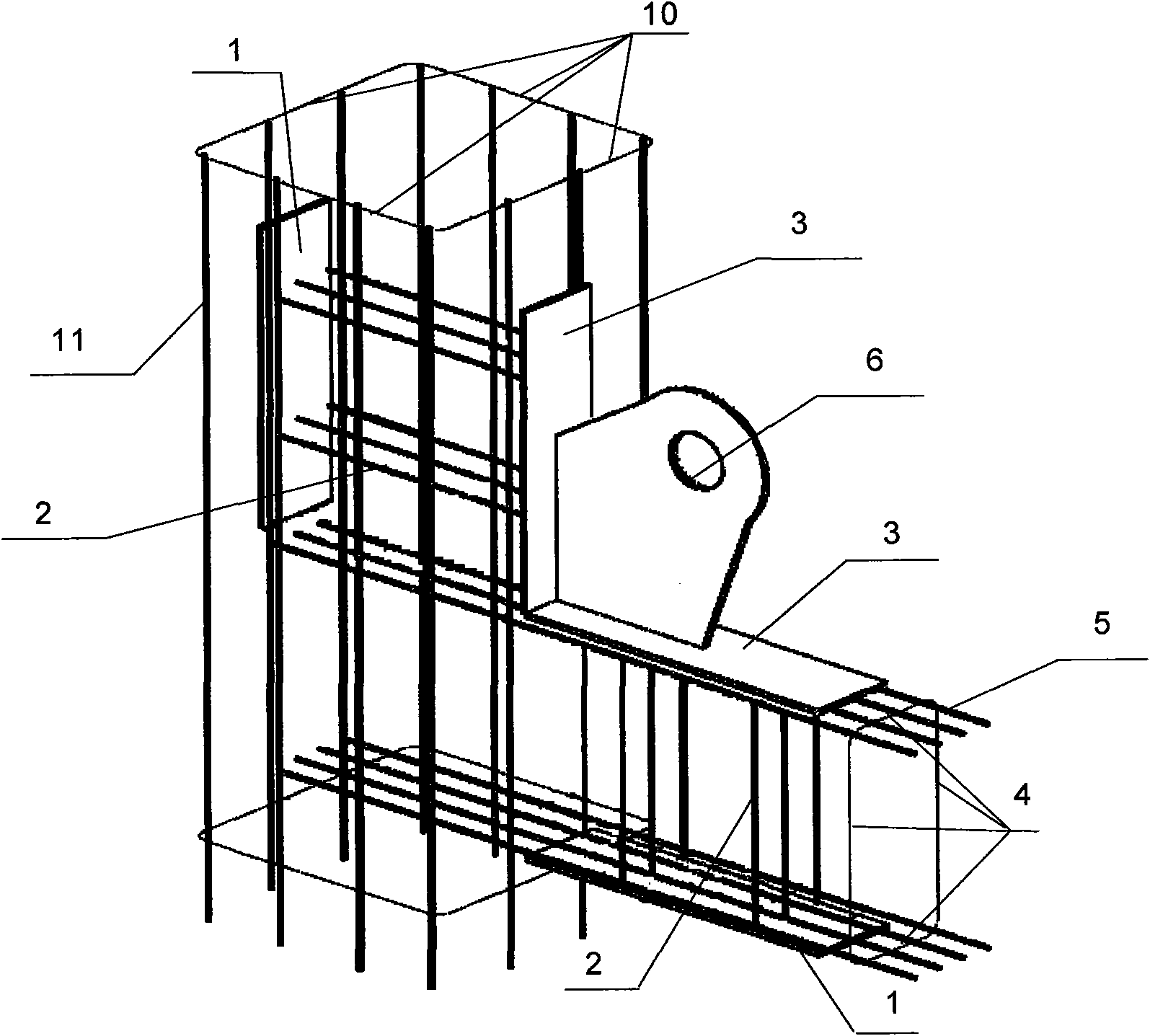
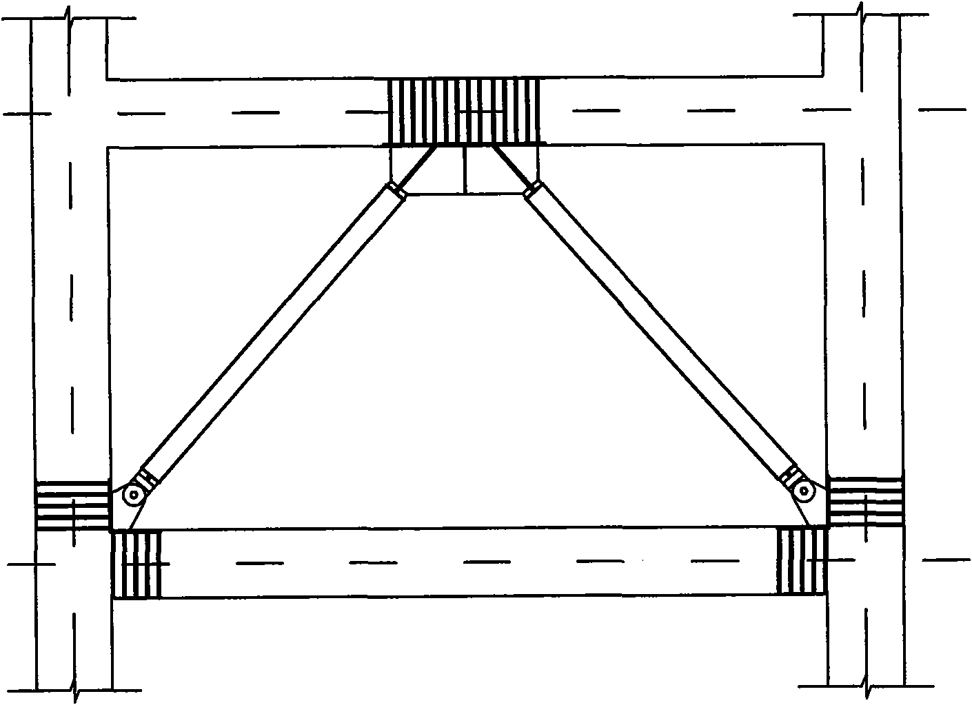
[0032] Taking the buckling-constrained support arranged in a herringbone shape as an example, the upper node of the support is as follows figure 1 As shown, the first steel plate 1 and the second steel plate 3 are respectively located outside the concrete beam stirrup 4, the concrete beam stirrup 4 is located outside the concrete beam longitudinal bar 5, and the first steel plate 1 and the second steel plate 3 are installed in the embedded parts. The threaded steel bar 2 is connected, the first steel plate 1 and the second steel plate 3 are respectively provided with plug welding holes, and the internal threaded steel bar 2 of the embedded part is welded at the plug welding holes with the first steel plate 1 and the second steel plate 3; the first support connection The gusset plate 6 is located below the second steel plate 3, the second support co...


PUM


Abstract

The invention belongs to the technical field of node connection of architectural structure, in particular to a vertical reinforced concrete component, that is, a connection node of a buckling-restrained brace (BRB), which consists of steel plates, internal-thread steel bars for embedded parts, internal stirrups for concrete beams, internal longitudinal bars for concrete beams, support connection node plates, support node stiffening plates, buckling-restrained supports, internal stirrups for concrete columns and internal longitudinal bars for concrete columns, wherein, two steel plates are connected by the internal-thread steel bars for embedded parts; plug welding holes are formed on the steel plates; steel bars are welded with a first steel plate and a second steel plate at the plug welding holes; a first support connection node plate is located at the upper part of the first steel plate or at the lower part of the second steel plate; a second support connection node plate is connected with the first support connection node plate; one end of the second support connection node plate is fixed at the upper part of the first steel plate or the lower part of the second steel plate, andthe other end thereof is connected with the buckling-restrained brace; and the support node stiffening plates are fixed at one side of the first support connection node plate. The invention solves the problems that steel support connection nodes are difficult to be mounted in a concrete frame, structural steel needs punching when being embedded in a concrete component, and stirrups and longitudinal bars are arranged with difficulties; and the invention has the advantages that the construction is convenient, the stress performance of connection is good, and steel materials can be saved, therefore, the invention has wide application prospect.

Description

technical field [0001] The invention belongs to the technical field of node connection of building structures, and in particular relates to a reinforced vertical concrete member-buckling constraint support connection node. Background technique [0002] Reinforced concrete frame structures are widely used and have a history of hundreds of years, and have the following advantages: [0003] (1) Take local materials. In reinforced concrete structures, sand and stones account for a large proportion, while cement and steel bars account for a small proportion. Sand and stones can generally be provided near the construction site. [0004] (2) Durable and fire-resistant. The steel bars are buried in the concrete, and the concrete protection is not easy to rust, thus improving the durability of the structure. When a fire occurs, the reinforced concrete structure will not be burned like a wooden structure, nor will it reach the softening temperature quickly and be destroyed like a s...

Claims


Application Information

Patent Timeline
Patent Type & Authority Applications(China)
IPC IPC(8): E04B1/41
Inventor 李国强孙飞飞胡大柱郭小康杨芳陈琛
Owner TONGJI UNIV ARCHITECTURAL DESIGN INST GRP CO LTD
Learn More