
Structure of constant velocity universal joint

A constant velocity universal joint and cage technology, which is applied in the direction of elastic couplings, mechanical equipment, couplings, etc., can solve the problem of large wear of the contact surface between the cage and the star sleeve, and reduce the constant velocity universal joint assembly Problems such as service life and unstable operation process, etc., achieve the effect of easy implementation of production process and process control, reliable production process and process control, and lower manufacturing precision requirements

Inactive Publication Date: 2010-03-17
叶祥宝 +1
View PDF0 Cites 11 Cited by
  • Summary
  • Abstract
  • Description
  • Claims
  • Application Information

AI Technical Summary

Problems solved by technology

There are the following defects: the contact surface between the spherical shell and the cage, and the contact surface between the cage and the star sleeve are relatively large and uneven, resulting in instability during operation, abnormal noise or blockage, and the cage is fragile. The service life of the constant velocity universal joint assembly is reduced above all. The faults of the ball cage in the prior art are manifested in the unsmooth cooperation, abnormal noise and blockage, and the severe faults are manifested in the cracking of the cage.

Method used


Image

  • Structure of constant velocity universal joint
  • Structure of constant velocity universal joint
  • Structure of constant velocity universal joint

Examples

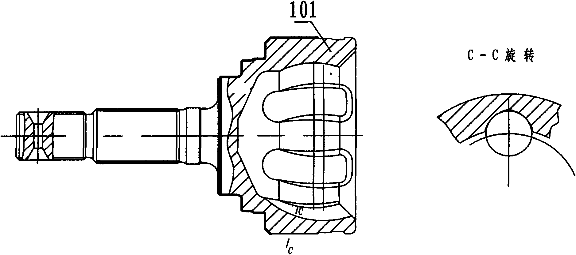
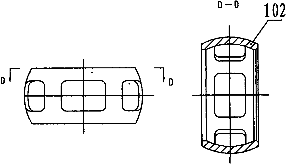
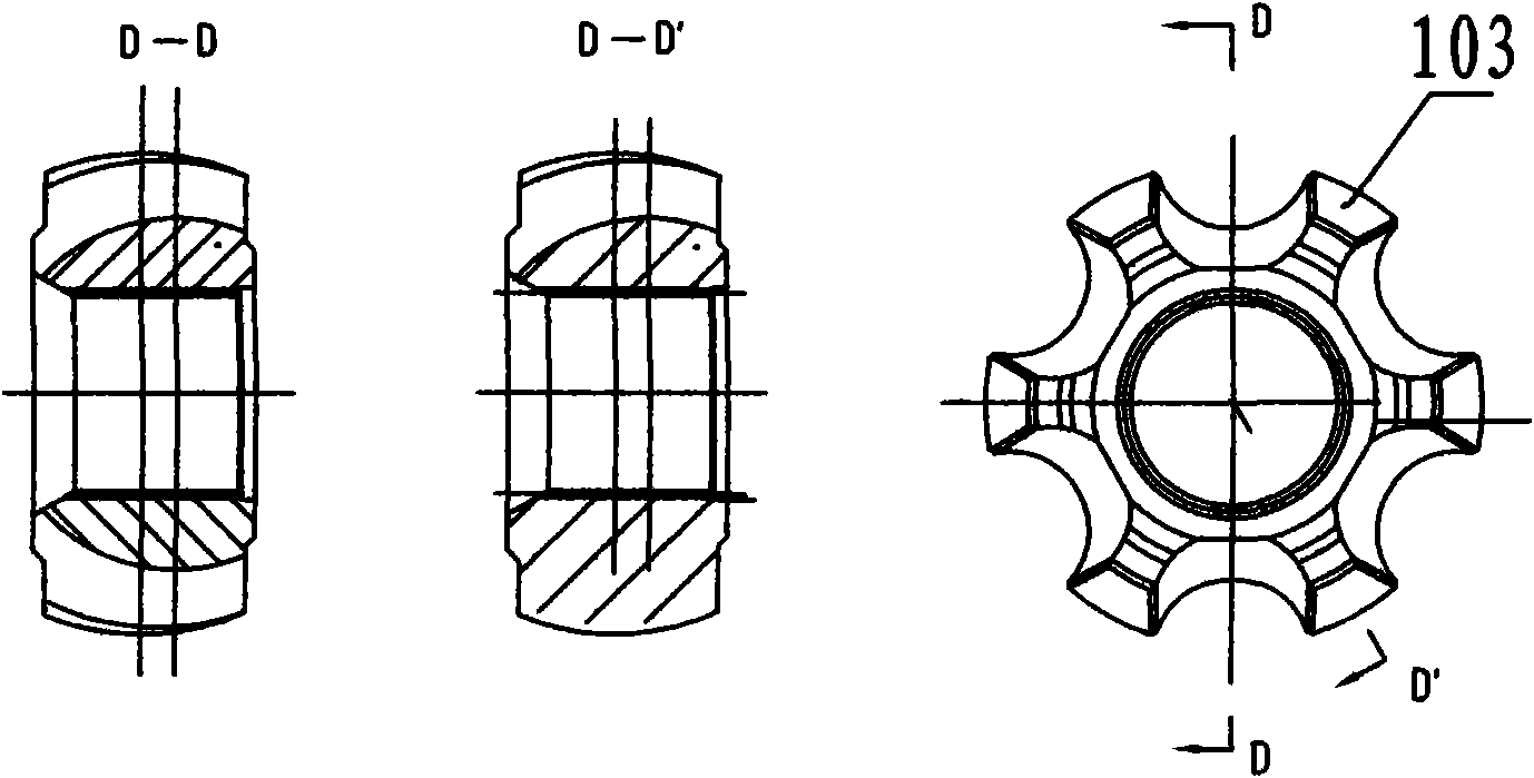

Embodiment Construction

[0025] The present invention will be further described below in conjunction with the accompanying drawings and specific embodiments.

[0026] Such as figure 1 , figure 2 , image 3 , Figure 4 , Figure 5 shown.

[0027] The inner surface of the spherical shell 101 in the prior art is evenly distributed with circular arc raceways, the inner surface is closely connected with the outer spherical surface of the cage 102, and the inner spherical surface of the cage 102 is closely connected with the outer spherical surface of the star sleeve 103, when the intermediate shaft (driving shaft) When the angle between 105 and the outer ball seat shaft (driven shaft) 106 changes, the inner spherical surface of the spherical shell 101 and the outer spherical surface of the cage 102 slip, and the inner spherical surface of the cage 102 and the outer spherical surface of the star sleeve 103 slip , so that the center of the steel ball is always located on the bisector of the angle betwe...


PUM


Abstract

The invention discloses a novel assembly structure of a constant velocity universal joint ball cage used for an automotive transmission system, which comprises a spherical shell (1), a retainer (2), astar-shaped sleeve (3), steel balls (4) and an outer spherical seat shaft (6). The inner spherical surface of the spherical shell (1) is connected with the outer spherical surface of the retainer (2), and the inner spherical surface of the retainer (2) is connected with the outer spherical surface of the star-shaped sleeve (3). The structure is characterized in that circular arcs of contact surfaces of the retainer (2) and the star-shaped sleeve (3) are changed, and the way that the radius of the circular arc at the middle section is larger than the radii of the circular arcs at two ends andthe circular arcs are smoothly connected is adopted. After the ball cage is assembled, gaps (7) and (8) at middle sections of the inner contact face and the outer contact surface of the retainer (2) are increased, and the abrasion is reduced; in addition, the structure is favorable for even dispersion of lubricating grease at the cavity of the constant velocity universal joint, increases the lubricating effect, promotes the comprehensive performance, and realizes promotion of torsional fatigue strength of an assembly by more than 20 percent. Meanwhile, the structure is easy to process and assemble, and relatively reduces the manufacturing cost.

Description

technical field [0001] The invention relates to a new structure of a constant velocity universal joint ball cage, in particular to a new assembly structure of a constant velocity universal joint ball cage used in a transmission system of an automobile chassis. Background technique [0002] The constant velocity universal joint assembly for automobiles is a mechanical part installed between the automobile differential or the final reduction gear and the wheels to transmit motion and torque. It consists of two sets or one set of output shaft and input shaft with an instantaneous angular velocity ratio equal to 1. It is a mechanical component that transmits motion and torque, and is composed of constant velocity universal joints, intermediate shafts and other components, and can synchronously change the working angle and perform telescopic sliding. [0003] Ball cage universal joint is the most widely used constant velocity universal joint. On the inner surface of the spherica...

Claims


Application Information

Patent Timeline
IPC IPC(8): F16D3/223
Inventor 叶祥宝付国庆
Owner 叶祥宝
Learn More