Downloading type plunger valve

A plunger valve and plunger technology, applied in the field of bottom-mounted plunger valves, can solve the problems of uneven pressing force between the valve ball sealing ring and the ball, errors, and the difficulty of ensuring accuracy of PE materials.

Inactive Publication Date: 2010-03-17
GUANGDONG LIANSU TECH INDAL
View PDF0 Cites 5 Cited by
  • Summary
  • Abstract
  • Description
  • Claims
  • Application Information

AI Technical Summary

Problems solved by technology

[0006] First, the socket depth of the valve body and the connecting pipe directly affects the axial distance between the sealing surfaces of the two valve balls, and affects the pre-pressing force
The socket depth is large, the pretightening force is large, the torque to open and close the valve is large, and the wear on the sealing surface of the valve ball is large; the socket depth is small, the pretightening force of the valve ball sealing surface is small, and there is a hidden danger of internal leakage
Moreover, it is difficult to ensure that the centerlines of the valve body and the connecting seat coincide during the socketing process. The frequent phenomenon is that the two centerlines do not coincide and form a certain angle, so that the pressing force between the valve ball sealing ring and the ball is between Uneven across the entire sealing strip
[0007] Second, from a manufacturing point of view, since the two valve ball sealing rings are located on the valve body and the connecting seat respectively, and the process positioning surfaces of the processing sealing ring installation rings are respectively located on these two parts, therefore, the two sealing ring installation rings There is a certain error in the axial distance after assembly due to the manufacturing of the positioning surface
[0008] 3. Large-diameter ball valves need electrofusion welding to connect the pipe and the valve body, and the electrofusion welding process is complicated and costly
[0009] Fourth, the compression force of the sealing ring behind the valve ball is too large, the sealing surface of the valve ball sealing ring opens outward, and the inner edge of the sealing surface of the sealing ring is in contact with the valve ball, not the entire sealing surface, and the sealing effect is checked; If it is too small, the seal will not be reliable
However, the structure achieves the design pressing force through two buckles located on the three parts, requiring high manufacturing precision, but it is difficult to guarantee the precision in PE material machining, and the assembly is difficult

Method used


Image

  • Downloading type plunger valve
  • Downloading type plunger valve
  • Downloading type plunger valve

Examples


Embodiment Construction

[0031] The present invention will be further described below in conjunction with the accompanying drawings.

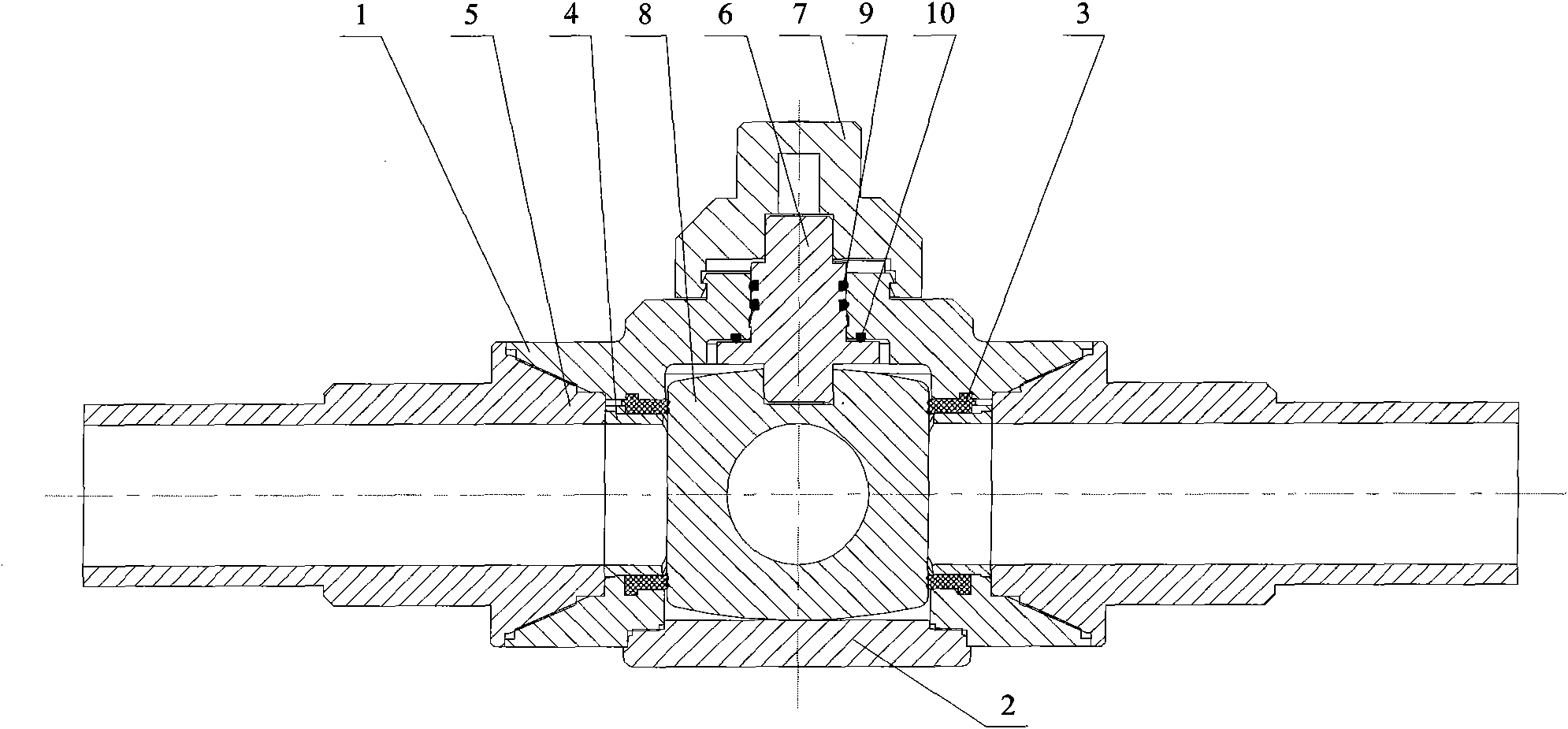
[0032] Refer to attached figure 1 The overall structure of the bottom entry plunger valve. Including valve body 1, valve bottom cover 2, plunger seal ring 3, plunger seal ring support ring 4, left and right connecting pipes 5, valve stem 6, valve stem cap 7, plunger 8, valve stem seal ring 9, valve stem end face sealing ring 10.

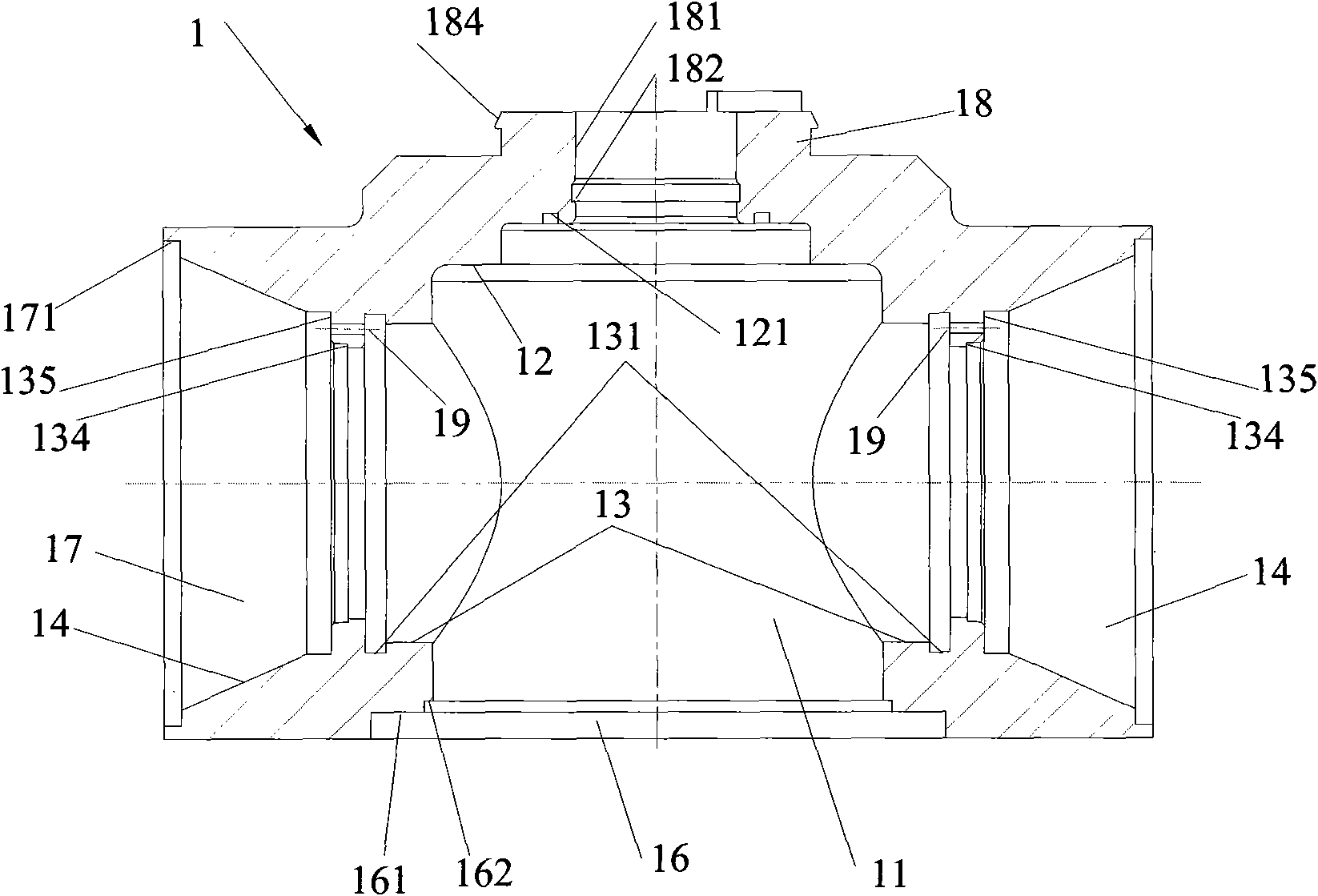
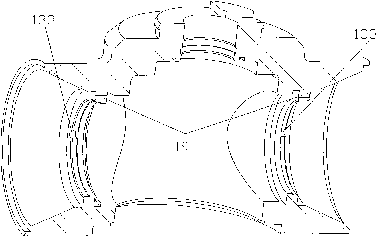
[0033] Refer to attached figure 2 , 3Shown is the structural diagram of the valve body 1 of the bottom-mounted plunger valve; the plunger chamber 11 of the valve body is an inner cylindrical cavity structure, and the lower part of the cylinder is in the form of an opening, which is processed with an end face or The conical surface 161, in the direction perpendicular to the axis of the plunger chamber 11 and located on both sides of the plunger chamber 11, has a coaxial cylindrical hole 13 for installing the plunger sealing ring 3 and is ...


PUM


Abstract

The invention relates to a downloading type plunger valve comprising a valve body, a plunger sealing ring, a support ring of the plunger sealing ring, a left connection tube, a right connection tube,a valve rod, a valve rod cap and a plunger, wherein a plunger chamber is arranged in the valve body and is a cylindrical hollow cavity which is longitudinally arranged, the plunger is arranged in theplunger chamber and is provided with a flow passage hole in a direction vertical to the axis of the plunger, the valve body is provided with an installation hole below the plunger chamber, and the installation hole is used for installing the plunger sealing ring and the plunger in the plunger chamber; the plunger valve also comprises a valve bottom cover, wherein the valve bottom cover correspondsto the installation hole, covers the installation hole and is in mutual butt fusion with the valve body.

Description

technical field [0001] The invention relates to the field of pipeline cut-off valves, in particular to a bottom-mounted plunger valve. Background technique [0002] With the widespread use of plastic gas pipelines, the United States took the lead in developing and producing plastic ball valves, which are widely used in plastic gas pipeline systems. People gradually realize the superiority of plastic ball valves in terms of performance / price, and gradually begin to use plastic ball valves instead of metal ball valves. [0003] Among the existing plastic ball valves, the small-diameter ball valves are integrally welded by hot-melt welding, and the large-diameter ball valves are welded by electrofusion. The hot-melt welding process is simple, the cost is low, and the precision is relatively low; the electric fusion welding process is complicated and the cost is high. [0004] In the structure of hot-melt welded valves, an integral side-mounted structure is generally used at p...

Claims


Application Information

Patent Timeline
Patent Type & Authority Applications(China)
IPC IPC(8): F16K5/04F16K5/08F16K27/02F16L13/02
Inventor 黄虹宾
Owner GUANGDONG LIANSU TECH INDAL
Why Eureka
Try Eureka