Method for compensating critical dimension

A technology of critical dimension and compensation method, applied in the field of exposure compensation, to achieve the effect of solving compatibility and saving manufacturing cost

Inactive Publication Date: 2010-03-17
NAN YA TECH
View PDF1 Cites 6 Cited by
  • Summary
  • Abstract
  • Description
  • Claims
  • Application Information

AI Technical Summary

Problems solved by technology

The novel critical dimension compensation method of the present invention can not only selectively correct the defects on the critical dimension produced during exposure, but also solve the compatibility problem between different exposure machines

Method used


Image

  • Method for compensating critical dimension
  • Method for compensating critical dimension

Examples


Embodiment Construction

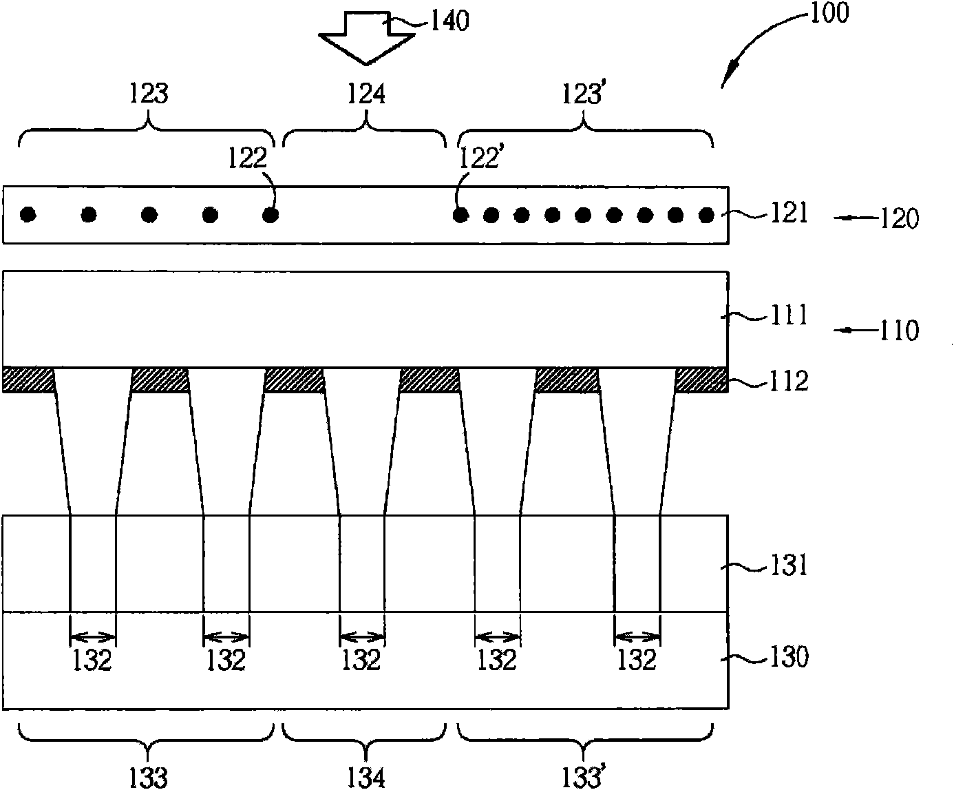
[0023] The present invention first proposes an exposure assembly. figure 1 A preferred embodiment of the exposure unit of the present invention is illustrated. The exposure assembly 100 of the present invention includes a main photomask 110 and an auxiliary photomask 120 . The main photomask 110 includes a main transparent substrate 111 and a main pattern 112 , and the device layout pattern can be defined in the substrate 130 through the main photomask 110 . In general, the master photomask 111 may also be referred to as a product photomask. The main transparent substrate 111 is usually a glass substrate. The glass substrate needs to have a high transmittance to the exposure light source. Generally speaking, the glass substrate is usually made of quartz material. The main pattern 112 is located on one side of the main transparent substrate 111, and its function is to block the exposure light source to form a predetermined pattern on the photoresist, but it is easy to be etc...


PUM


Abstract

The invention discloses a method for compensating critical dimension, which comprises the following steps: firstly, providing a light source and a primary photomask; and secondly, providing an auxiliary photomask which is orderly arranged with the primary photomask and comprises an auxiliary transparent substrate and a shielding element positioned in the auxiliary transparent substrate. Therefore,the light of the light source orderly passes through the auxiliary photomask and the primary photomask to the substrate, and the light can generate different reaction when passing through the shielding element, so the light can compensate the critical dimension of element layout patterns.

Description

technical field [0001] The present invention relates to an exposure compensation method, in particular, to a critical dimension compensation method in exposure. Background technique [0002] In the production process of integrated circuits, photolithography has long been an indispensable technology. The photolithography process is mainly to form the designed pattern, such as circuit pattern, contact hole pattern, etc., on one or more photomasks, and then use the stepping and scanning of the pattern on the photomask through the exposure process. The machine (stepper&scanner) transfers to the photoresist layer on the semiconductor chip. Only with a precise photolithography process can the complex layout pattern be accurately and clearly transferred to the semiconductor chip. [0003] As the device size of dynamic random access memory (DRAM) shrinks day by day, how to improve the critical dimension uniformity (CDU) of the photolithography process becomes a key issue. Theoret...

Claims


Application Information

Patent Timeline
Patent Type & Authority Applications(China)
IPC IPC(8): G03F1/14G03F7/20G03F1/38G03F1/72
Inventor 陈宣克汪美里金持正范倍诚
Owner NAN YA TECH
Why Eureka
Try Eureka