
Automatic assembling machine of light touch switch

An automatic assembly machine, tact switch technology, applied in electrical switches, electrical components, circuits, etc., can solve the problems of crushed shrapnel, riveting failure, and reduced machine assembly efficiency.

Inactive Publication Date: 2010-03-17
温州和泰电子有限公司 +1
View PDF0 Cites 14 Cited by
  • Summary
  • Abstract
  • Description
  • Claims
  • Application Information

AI Technical Summary

Problems solved by technology

They have the following defects: (1) The shrapnel is tilted when placed in the base and rests on the side wall of the base. When the button is installed, the shrapnel will break and deform, resulting in defective products
(3) The button has been shifted when taking the material, so putting it into the base will crush the inner wall of the base or the button, and make the shrapnel that has been placed in the base jump out or jump to the side wall, eventually causing the shrapnel to be crushed and the button to be damaged. Defects caused by crushing and base crushing
(4) The upper cover has been shifted when grasping (or sucking), so when the base is covered, the rivet column will be crushed or the product will not be riveted
(5) The upper cover or button cannot be removed when it is grasped (or sucked) on the material belt or track, and the product has no upper cover or no button after assembly, resulting in adverse consequences
(6) Waiting when the button or the upper cover is short of material, the efficiency of machine assembly will decrease

Method used


Image

  • Automatic assembling machine of light touch switch
  • Automatic assembling machine of light touch switch
  • Automatic assembling machine of light touch switch

Examples


Embodiment 1

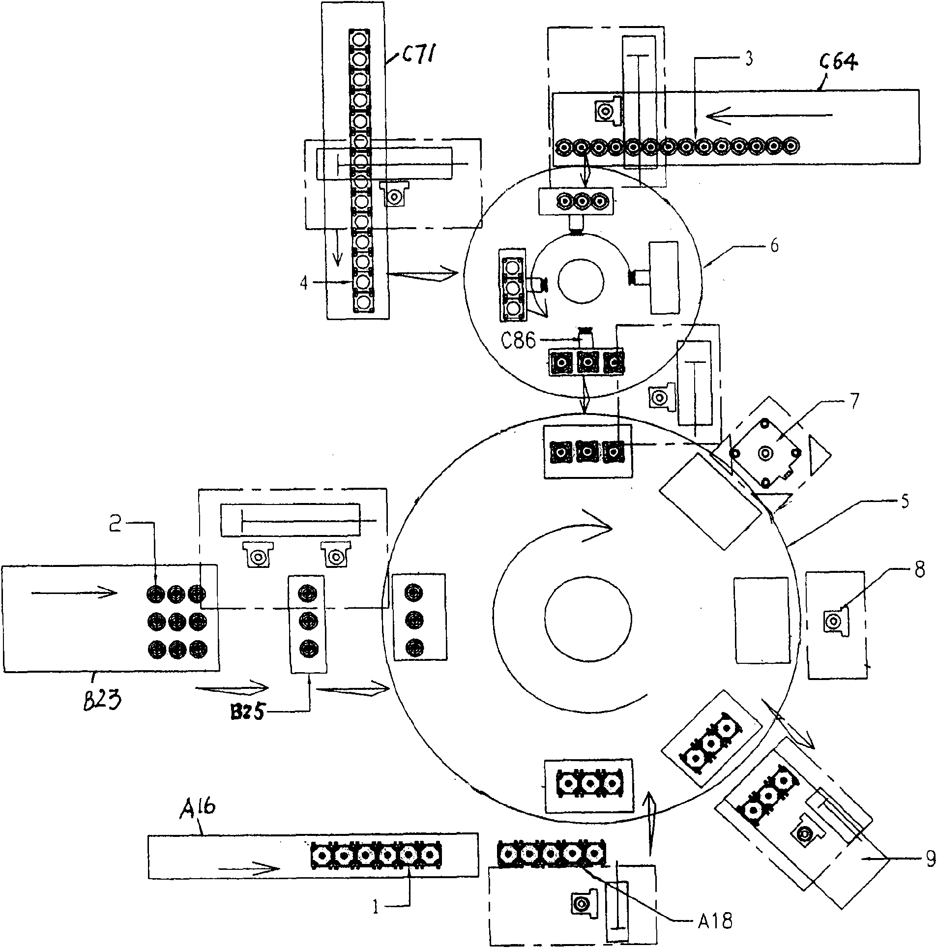
[0021] see figure 2 , an automatic assembly machine for tact switches, which includes an assembly jig, the assembly jig is fixed on the assembly main plate 5, and the assembly jig on the assembly main plate 5 is relatively several positioning stations and an indexing center plate 6 during rotation. , fix the transfer positioning station on the indexing station plate 6, and connect the air pipe joint C86 to the transfer positioning station. When there is material put into the transfer positioning station, vacuum suction will be generated, and the vacuum suction will stop when the material is taken away; when assembling the main disk 5 A base vacuum suction mechanism and a shrapnel vacuum suction mechanism are arranged on the side, and a button upper cover vacuum suction mechanism is arranged beside the indexing center plate 6.

[0022] see figure 2 , the assembly fixture is divided into assembly fixture A, assembly fixture B, assembly fixture C, assembly fixture D, assembly ...

Embodiment 2

[0039] Such as Figure 10 As shown, the assembly jig moves to the next station for assembly after each assembly is completed ( Figure 10 Shown by the arrow R in the middle), instead of rotating to the next station in the first embodiment (see figure 2 The assembly jig A in the assembly is rotated to the position of the assembly jig B), and other actions are the same as in the first embodiment.


PUM


Abstract

The invention relates to an automatic assembling machine of a light touch switch, comprising an assembling jig; the assembling jig is fixed on an assembling main disc or an assembling moving belt andcorresponds to a plurality of positioning stations and a scale midstation disc when in rotating or moving; a transfer positioning station is fixed on the scale midstation disc, the transfer positioning station is connected with an air pipe joint; vacuum absorbing is generated when materials are put into the transfer positioning station, and the vacuum absorbing is stopped when materials are removed from the transfer positioning station; the side of the assembling main disc or the assembling moving belt is provided with a vacuum absorbing mechanism of a bottom seat and a vacuum absorbing mechanism of an elastic piece; and the side of the scale midstation disc is provided with a vacuum absorbing mechanism of a button upper cover. The automatic assembling machine improves the assembling speedand assembling quality of the light touch switch.

Description

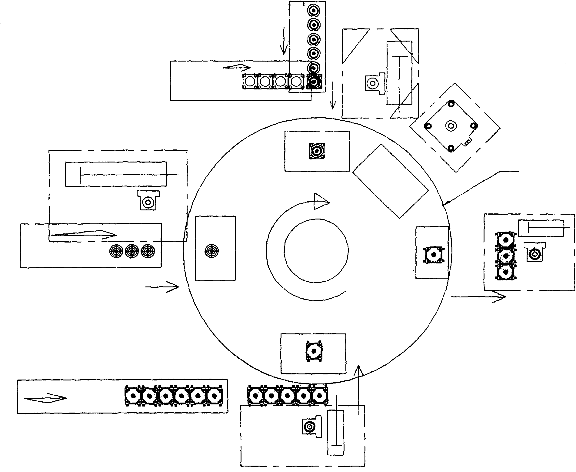
technical field [0001] The invention relates to a process equipment for making switches, in particular to an automatic assembly machine for light touch switches. Background technique [0002] The tact switch is generally composed of a base, a shrapnel (or a reed and a dome), a dust-proof film, a button, and an upper cover. During the assembly process, the button and the upper cover are directly taken from the material belt or the track and put into the base. The positioning on the material belt or the track is not accurate, and the deviation has occurred when the material is taken out. There are two situations in the prior art. For the first case see figure 1 , the shrapnel is assembled directly from the shrapnel track (or after being cut off from the material belt); the upper cover and the button are also directly taken from the track (or from the material belt) for assembly, and there is no intermediate positioning for both assemblies before assembly . Another situatio...

Claims


Application Information

Patent Timeline
IPC IPC(8): H01H11/00
Inventor 李永强
Owner 温州和泰电子有限公司
Learn More