Method for measuring the shpericity of spherical profiles

A roundness measurement and profile technology, which is applied in the field of roundness measurement for round profiles, can solve problems such as inability to reflect profile features, uncertain center of circle, etc.

Inactive Publication Date: 2010-03-17
ZUMBACH ELECTRONICS
View PDF4 Cites 19 Cited by
  • Summary
  • Abstract
  • Description
  • Claims
  • Application Information

AI Technical Summary

Problems solved by technology

In addition, the center of the circle is not determined in space, which leads to, for example, when the shape deviation is asymmetric, the determined silhouette has periodic symmetry related to the number and arrangement of tangent lines, which cannot reflect the real silhouette characteristics

Method used


Image

  • Method for measuring the shpericity of spherical profiles
  • Method for measuring the shpericity of spherical profiles
  • Method for measuring the shpericity of spherical profiles

Examples


Embodiment Construction

[0053] The invention will be described in more detail below with reference to examples, with reference to the schematic drawings, which illustrate the method steps according to the invention.

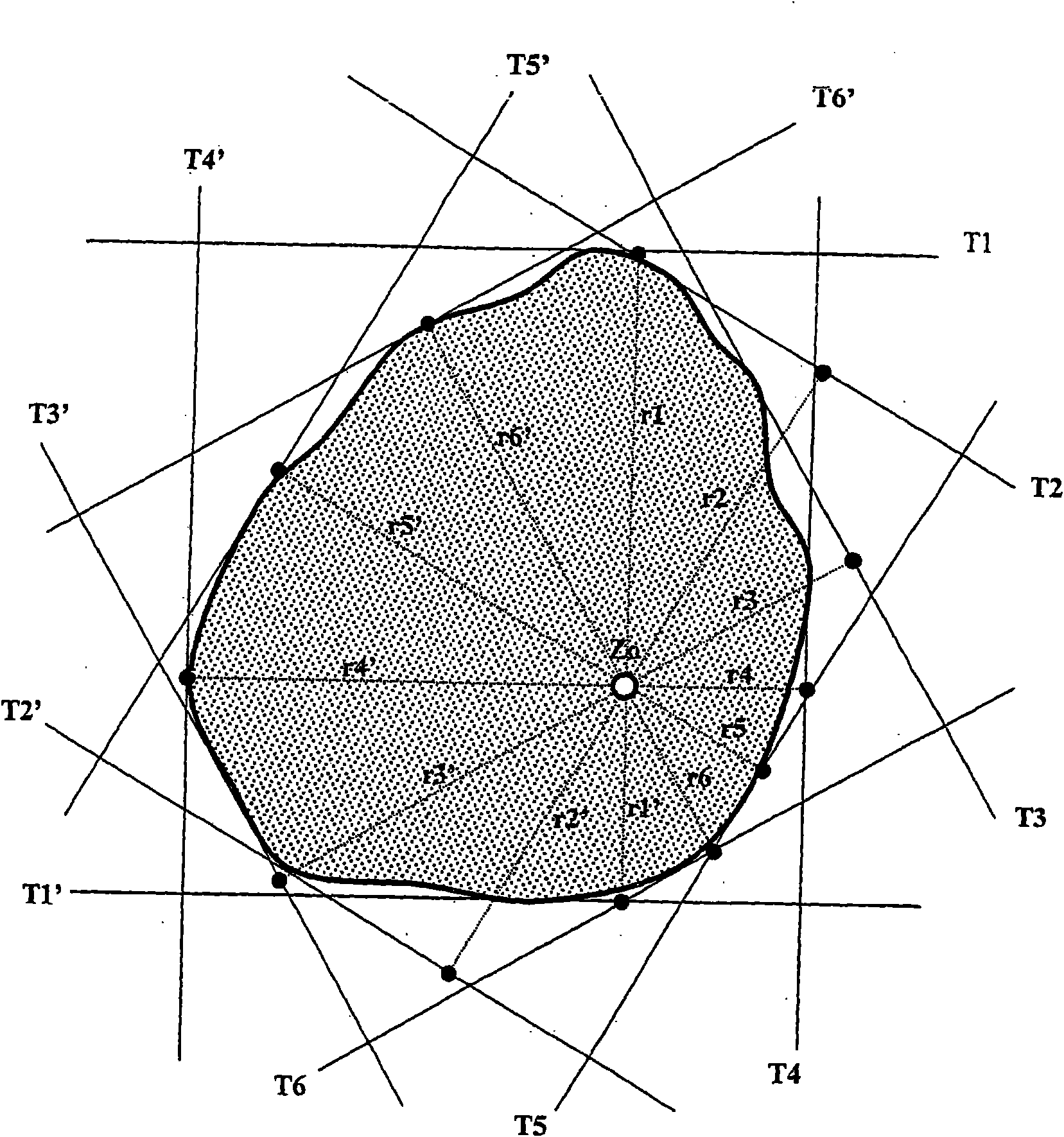
[0054] figure 1 A cross-section of a round profile to be tested is shown, and the outer contour of the round profile is shown by a thick solid line. On this round profile, a total of 12 projected edges are arranged by means of six laser scanners, said projected edges forming the tangent T 1 , T 2 , T 3 , T 4 , T 5 , and T 6 and T 1’ , T 2’ , T 3’ , T 4’ , T 5’ , and T 6’ . Here, the tangent to T 1 , T 1’ ; T 2 , T 2’ ; T 3 , T 3’ ; T 4 , T 4’ ; T 5 , T 5’ and T 6 , T 6’ Each belongs to a laser scanner. A total of six laser scanners are therefore used, the round profile to be measured being located entirely in the measuring field of these laser scanners.

[0055] The center Z of the measuring field of the measuring device is usually more precisely determined and...


PUM


Abstract

The invention relates to a method for measuring the sphericity or for measuring the shape deviation of spherical profiles in rolling trains that displace in the longitudinal direction thereof. According to the invention, at least three shadow edges that are adjacent to the spherical profile that is to be measured, that surrounds said spherical profile and that forms a polygon are produced and measured in a known manner, with the aid of a measuring device having at least two laser scanners that respectively comprise a light-sensitive sensor and a laser, and the corresponding tangents are calculated from said result. Said method is characterised in that a) prior to measurment, a centre (Z0) in the measuring field of the measuring device is calibrated and determined provided that said type ofcentre (Z0) has not already determined, b) perpendiculars (r1, - r6') from the centre (Z0) to the tangents (T1, bis T6' ) and also the distance from the centre (Z0) to the tangents (T1 - T6' ) is calculated, c) the corner points (A - K) of the polygon surrounding the spherical profile are calculated, a contour is determined, d) a reference circuit is determined in relation to the contour such that i) the quadratic shape deviation of the contour reaches a minimum in relation to said reference circuit, ii) said reference circuit represents the smallest possible circuit that adapts to the contour, iii) said reference circuit representing the largest possible circuit that adapts to the contour, or iv) the reference circuit together with an additional circuit that is concentric to the reference circuit surrounds the contour at a minimal radial distance, e) the diameter (Dref) of the reference circuit is calculated and the reference centre (Zp) is determined from the position in the cavitythat represents the centre point of the reference circuit and f) at least two vectors are calculated from said reference centre (Zp) to the contour and the ovality is determined from said data.

Description

technical field [0001] The invention relates to a method for roundness measurement or shape deviation measurement of a round profile advancing in the longitudinal direction in a rolling mill, wherein in a manner known per se by means of a measuring device having at least two laser scanners, Generating and measuring at least three polygon-forming projected edges abutting against and enclosing the round profile to be measured, and calculating corresponding tangents therefrom, the laser scanner each has a photosensitive sensor and a laser. Background technique [0002] In the steel industry, so-called long products / bars are rolled in special rolling mills / mill trains to obtain the desired end product. If these elongated products are to be rolled into round bars, they are usually rolled in a three-high finishing stand / stand (Gerüst) with several rolling modules (usually 3-high modules / 3-high groups). These elongated products are rolled to finished size and conveyed to a cooling...

Claims


Application Information

Patent Timeline
Patent Type & Authority Applications(China)
IPC IPC(8): G01B11/24G01B11/245B21B38/04
CPCG01B11/2408B21B38/04G01B11/245
Inventor U-P·施图德
Owner ZUMBACH ELECTRONICS
Why Eureka
Try Eureka