Apparatus for conveying substrates, method and apparatus for locating substrates

A substrate handling and substrate technology, which is applied in transportation and packaging, lighting and heating equipment, furnace components, etc., can solve the problems that devices cannot be combined, and achieve the effect of simplified structure and simple structure

Inactive Publication Date: 2010-03-24
DAINIPPON SCREEN MTG CO LTD
View PDF2 Cites 33 Cited by
  • Summary
  • Abstract
  • Description
  • Claims
  • Application Information

AI Technical Summary

Problems solved by technology

Therefore, in the case where the aforementioned inclination angle does not match the posture of the substrate in the device of the upstream process or the downstream process, there is a problem that the device described in Patent Document 2 cannot be directly combined with the device of the upstream process or the downstream process.

Method used


Image

  • Apparatus for conveying substrates, method and apparatus for locating substrates
  • Apparatus for conveying substrates, method and apparatus for locating substrates
  • Apparatus for conveying substrates, method and apparatus for locating substrates

Examples


no. 1 approach

[0055]

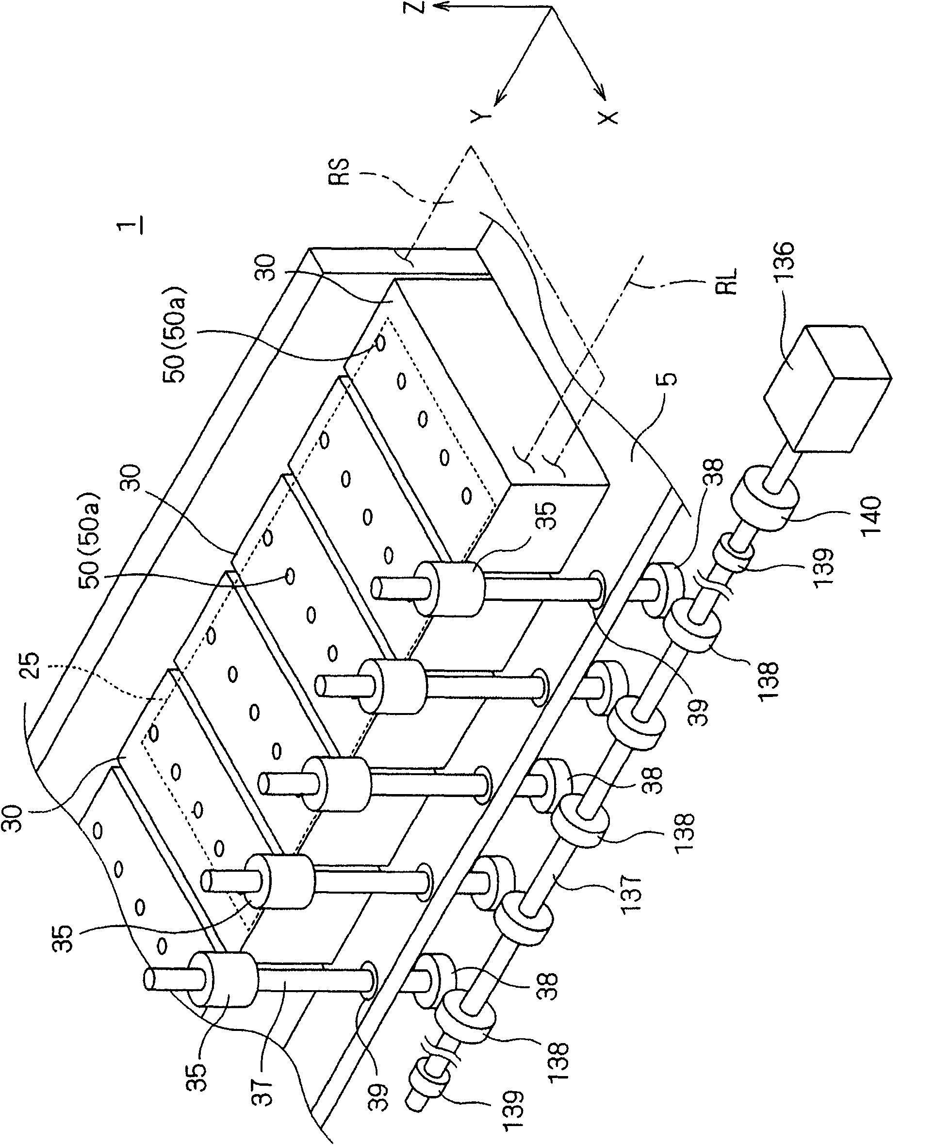
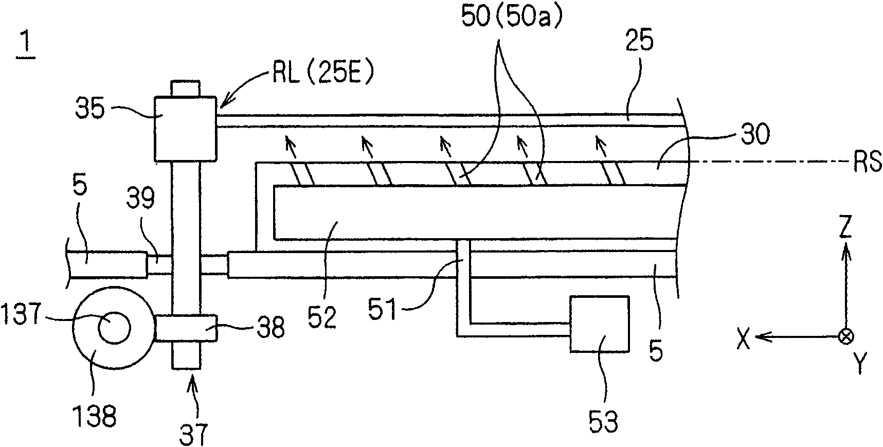
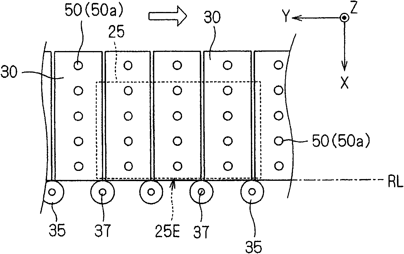
[0056] figure 1 It is a perspective view which shows the schematic structure of the main body of the board|substrate conveyance apparatus 1 which concerns on embodiment of this invention. in the figure 1 In , for the convenience of illustration and description, it is defined that the Z-axis direction represents the vertical direction, and the XY plane represents the horizontal plane. However, these are defined for the convenience of grasping the positional relationship, and do not limit each direction described below. The same applies to the following figures. figure 2 This is a cross-sectional view obtained by cutting a perspective view of the main body of the board transfer device 1 in the XZ plane.

[0057] figure 1 The illustrated substrate transfer apparatus 1 can move from the (+Y) direction (upstream side) to the (-Y) direction (downstream side), keeping the rectangular substrate 25 floating on the substrate transfer table 30 without changing the substra...

no. 2 approach

[0075] In the first embodiment, one type of air ejection hole 50 is used, which is a composite direction of the first direction ((+Z) direction) and the second direction ((+X) direction), but it is not limited thereto. That is, the first air ejection hole 50a that ejects compressed air toward an oblique direction and the air ejection hole 50 (second air ejection hole 50b) that ejects compressed air toward a direction perpendicular to the lower surface of the substrate 25 are used in combination, The present invention can also be implemented.

[0076] As the main form of such combinations, such as Figure 6 As shown schematically by classification, (a) about the first air ejection hole 50a ( Figure 6 in the white circle) and the second air ejection hole 50b ( Figure 6 There are 3 types of arrangements of the black circles in (b), and there are 3 types of arrangements of substrate transfer tables in (b), so that there are 9 types in total.

[0077] In the following, the abo...


PUM


Abstract

The present invention provides an apparatus for conveying substrates, capable of preventing the substrates from deformation or damage due to flexibility of the substrates and conveying the substrateswithout contact. Compressed air for spraying to a lower surface of a horizontal substrate (25) is applied in a face manner from the lower of the substrate (25). Thus, the substrate (25) is floated upward and is subjected to an action force toward a baseline (RL) side, such that a fiducial edge (25E) of the substrate (25) which is subjected to the action force by the compressed air is contacted toan array of conveying rollers (35) arranged along the baseline (RL). By means of the drive of the conveying rollers (35), the substrate (25) is conveyed horizontally in a floating mode that the fiducial edge (25E) and the conveying rollers (35) are contacted mutually.

Description

technical field [0001] The present invention relates to a non-contact substrate transfer device, a substrate positioning method, and a device for transferring a substrate by blowing gas to the lower surface of the substrate to float the substrate. Background technique [0002] There is known an apparatus that transports the substrate in a non-contact state by spraying compressed gas onto the lower surface of the substrate used in the manufacture of liquid crystal panels or semiconductors to float the substrate. Patent Document 1 proposes an apparatus in which a gas blowing unit is provided to float a substrate, and conveying rollers as substrate conveying units are provided on both sides of a substrate conveying line parallel to the advancing direction of the substrate to clamp the substrate, thereby carry out. [0003] In addition, Patent Document 2 proposes an apparatus that floats and tilts a substrate, and transports it by a single-side substrate transport unit provided...

Claims


Application Information

Patent Timeline
Patent Type & Authority Applications(China)
IPC IPC(8): B65G49/06B65G49/07B65G51/03B65G13/00B65G15/00B65G47/24G02F1/1333H01L21/677H01L21/68
CPCB65G47/911B65G49/061B65G49/063B65G2249/045G02F1/1303H01L21/67784
Inventor 谷口竹志
Owner DAINIPPON SCREEN MTG CO LTD
Why Eureka
Try Eureka