Flushing device

A flushing device, flushing technology, applied in valve devices, water supply devices, indoor sanitary piping devices, etc., can solve the problems of energy consumption, high cost, complexity, etc., and achieve the effect of prolonging the use time

Inactive Publication Date: 2010-03-24
DELTA ELECTRONICS INC
0 Cites 3 Cited by

AI-Extracted Technical Summary

Problems solved by technology

[0002] Traditional inductive flushing devices are used in inductive urinal flushers or inductive faucet flushers, etc. They are designed and developed in accordance with the specifications of the mains power supply, but DC power is still used in the electronic control components, so the use of electricity requires Converting AC to DC can be used by electronic control circuits. A set of transformers is generally required for voltage conversion. The use of transformers will result in huge energy consumption (loss of heat or magnetic energy). If this AC product is used with a solenoid valve It is a non-holding solenoid valve, and the energy consumption of opening the solenoid valve for a long time is very considerable
[0003] The above-mentioned AC flushing equipment requires a traditional transformer, resulting in high cost and large volume
Furthermore, the assembly will be more difficult and complicated than other products of the same type. In addition, the power line must be reserved in the building when the product is installed, so that the product cannot be popularized.
[0004] Regarding the inductive flushing device with DC power supply, the power supply of this series of products is DC, which are all designed to be provided by batteries. The product installation is very con...

Method used

Furthermore, in the present embodiment, the flushing device 1 also includes a capacitor 17 and a diode 18, the capacitor 17 is used to pre-store the charge generated by the solar cell 11, and the solar cell 11 and the capacitor 17 are connected in parallel after the terminal N , the terminal N is electrically connected to the boost unit 12 . Furthermore, the solar cell 11 is electrically connected to the anode of the diode 18 , and the cathode of the diode 18 is electrically connected to the terminal N, so as to prevent the current from flowing backward to the solar cell 11 .
In summary, when the flushing device of the present invention can use a small-area solar cell or when the ambient light source is insufficien...

Abstract

A flushing device comprises a control module, a solar cell and a rechargeable cell. The control module is used for controlling the flushing device to operate. The rechargeable cell is connected with the solar cell in parallel at a power output end. The power output end is electrically connected with the control module to provide power to the control module.

Application Domain

Technology Topic

Image

  • Flushing device
  • Flushing device

Examples

  • Experimental program(2)

Example

[0024] first embodiment
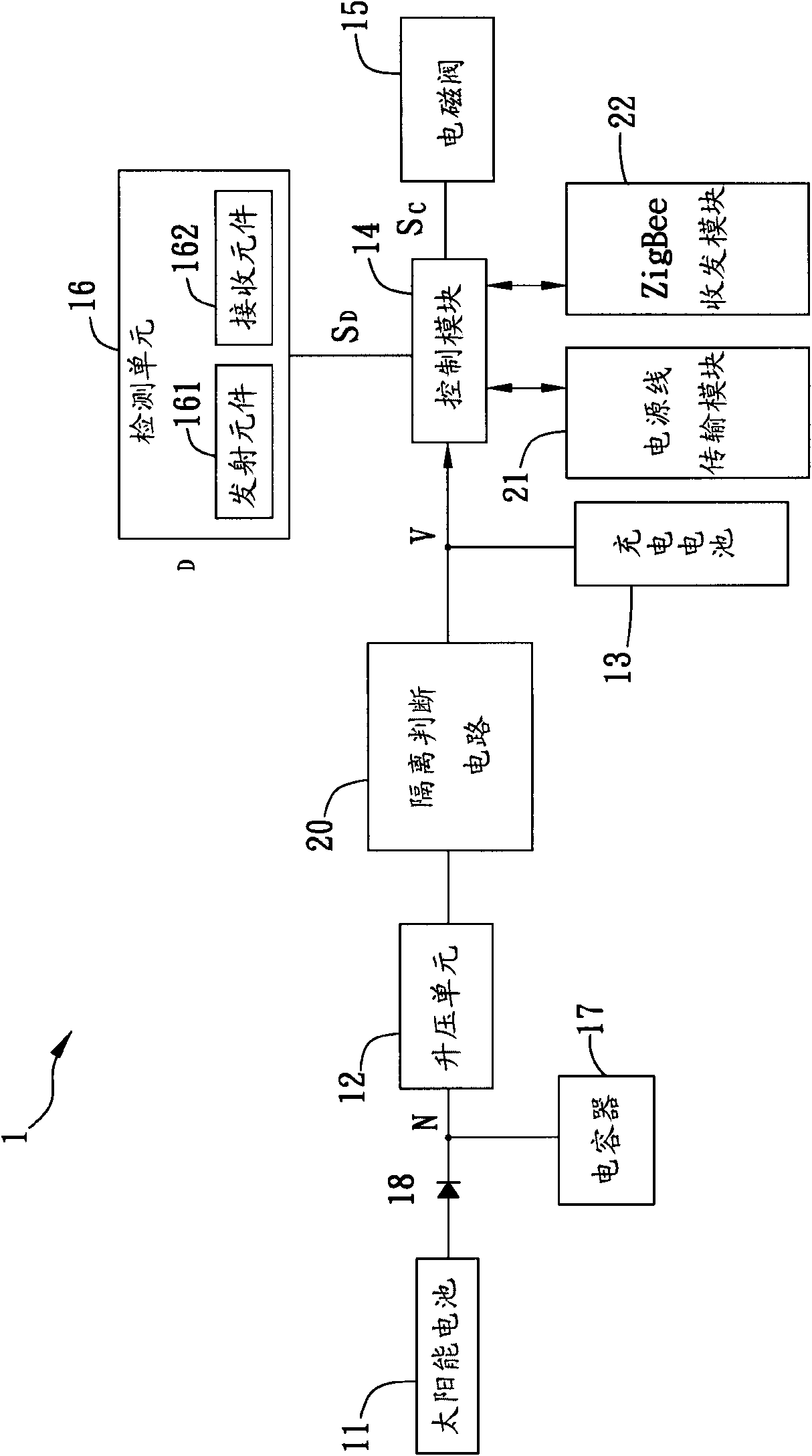
[0025] figure 1 It is a schematic diagram of the flushing device according to the first embodiment of the present invention. The flushing device 1 mainly includes a solar cell 11 , a booster unit 12 , a rechargeable battery 13 , a control module 14 , a solenoid valve 15 and a detection unit 16 .
[0026] In this embodiment, the solar cell 11 converts the received ambient light source into a voltage. When the operating voltage of the solar cell 11 is lower than the electromotive force of the rechargeable battery 13 (for example, when a small area of ​​solar cell is used or the ambient light source is insufficient), the solar cell The battery 11 is electrically connected to a boosting unit 12, which can be a booster, and is connected in parallel with the rechargeable battery 13 to the power output terminal V, and the power output terminal V is electrically connected to the control module 14, for the control module 14 provides power.
[0027] The solenoid valve 15 is a switch for flushing the flushing device 1 . The control module 14 includes a microcontroller, and the control module 14 is electrically connected to the solenoid valve 15 for controlling the opening and closing of the solenoid valve 15 .
[0028] Furthermore, the flushing device further includes an isolation judgment circuit 20, one end of which is electrically connected to the boosting unit 12, and the other end is connected to the power output terminal V. The isolation judgment circuit 20 can prevent the control module 14 from extracting current from the solar cell 11, resulting in The voltage of the power output terminal V drops, and the rechargeable battery 13 cannot be charged. However, when the load with low power consumption generally has little influence on the converted voltage of the solar cell 11 , the isolation judgment circuit 20 can be omitted.
[0029] Furthermore, in this embodiment, the washing device 1 further includes a capacitor 17 and a diode 18. The capacitor 17 is used to pre-store the charges generated by the solar cell 11. After the solar cell 11 and the capacitor 17 are connected in parallel to the terminal N, the terminal N is connected to the terminal N. It is electrically connected to the boosting unit 12 again. Furthermore, the solar cell 11 is electrically connected to the anode of the diode 18 , and the cathode of the diode 18 is electrically connected to the terminal N, so as to prevent the current from flowing back to the solar cell 11 .
[0030] The flushing device 1 of the present invention is a solar induction flushing device, which uses two power sources, a solar cell 11 and a rechargeable battery 12 , as power supplies. When the ambient light source illuminates the solar cell 11 and charges the solar cell 11 , the electromotive force of the solar cell 11 increases, and the voltage of the power output terminal V also increases after being boosted by the boosting unit 12 . When the voltage of the power output terminal V is higher than the electromotive force of the rechargeable battery 12 , the solar battery 11 becomes the main working power source, supplies power to the control module 14 , and charges the rechargeable battery 12 . When the intensity of the ambient light source is weak, the electromotive force of the solar cell 11 also decreases, and the voltage of the power output terminal V after being boosted by the boosting unit 12 also decreases. When the voltage of the power output terminal V is lower than that of the rechargeable battery When the electromotive force of 12 is reached, the rechargeable battery 12 is automatically converted into the main power supply. Therefore, the solar cell 11 can charge the rechargeable battery 12 after being boosted by the boosting unit 12 , or directly supply the load for use, and the rechargeable battery 12 can ensure a stable and continuous power supply for the load.
[0031] Furthermore, the detection unit 16 is electrically connected with the control module 14 to detect whether there is a user in the environment where the flushing device 1 is located, and can transmit a detection signal S D to the control module 14, and the control module 14 is based on the detection signal S D , output the driving power Sc to the solenoid valve 15 to control the opening and closing of the solenoid valve 15 . In this embodiment, the detection unit 16 can be an infrared detection unit, and the detection unit 16 includes a transmitting element 161 and a receiving element 162 . Taking the sensor flush urinal as an example, when the user starts to use the transmitting element 161 An infrared signal is emitted, which is reflected by the user and received by the receiving element 162, so that the existence of the user can be known; after that, if the user leaves, the receiving element 162 cannot receive the reflected infrared signal, and it can be known that the user has left , after the detection unit 16 senses that the user leaves, the control module 14 can provide at least one driving power Sc to the solenoid valve according to the user's usage time and/or usage frequency, control the switch of the solenoid valve 15, and control the flushing device 1 Flush time.
[0032] Furthermore, the flushing device is also provided with a power line transmission module 21 or a Zigbee transceiver module 22, which carries out bidirectional data transmission to the control module 14. The control module 14 can transmit the electromotive force of the rechargeable battery 13 and the sensing data such as the number of times the flushing device 1 is used through the power supply. The line transmission module 21 or the wireless network ZigBee transceiver module 22 outputs the output, and the main control terminal can correct the control loop program of the control module 14 through the power line transmission module 21 and the Zigbee transceiver module 22 .

Example

[0033] Second Embodiment
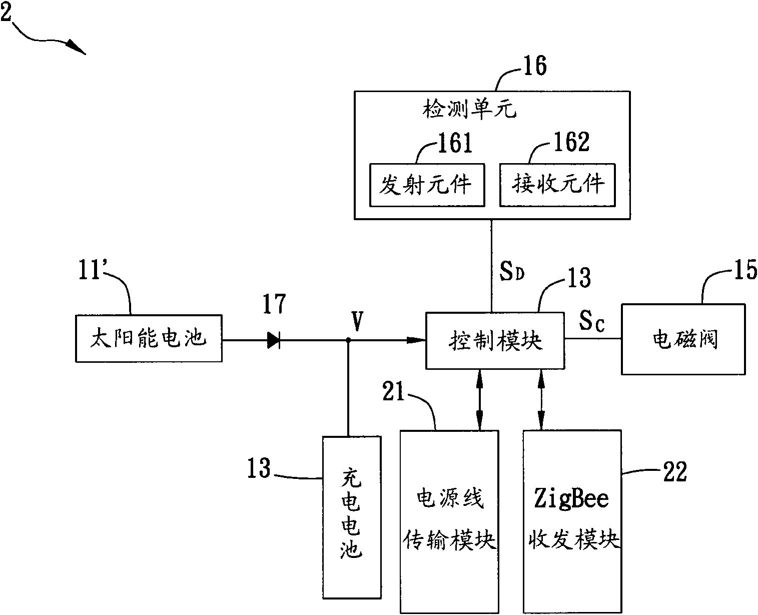
[0034] figure 2 It is a schematic diagram of a flushing device according to the second embodiment of the present invention. The flushing device 2 mainly includes a solar cell 11', a rechargeable battery 13, a control module 14, a solenoid valve 15 and a detection unit 16. The difference between the washing device 2 and the first embodiment is that the working voltage of the solar cell 11' is greater than the electromotive force of the rechargeable battery 13, so the washing device 2 can have no capacitor 17, booster unit 12 and isolation judgment circuit 20.
[0035]In this embodiment, the flushing device 2 uses two power sources, the solar cell 11 ′ and the rechargeable battery 13 , as the power supply at the same time, and the two power sources are used in cooperation with each other to provide the power of the control module 14 . When the ambient light source illuminates the solar cell 11' and charges the solar cell 11', the electromotive force of the solar cell 11' increases, and the voltage of the power output terminal V also increases accordingly. When the voltage of the power output terminal V is higher than the electromotive force of the rechargeable battery 13, the solar battery 11' becomes the main working power source, supplies power to the control module 14, and charges the rechargeable battery 13. When the intensity of the ambient light source is weak, the electromotive force of the solar cell 11 ′ also decreases, and the voltage of the power output terminal V also decreases. When the voltage of the power output terminal V is lower than the electromotive force of the rechargeable battery 13 , the rechargeable battery 13 Automatic conversion to the main power supply. Therefore, the solar cell 11' can charge the rechargeable battery 13, or directly supply the load for use, and the rechargeable battery 13 can ensure a stable and continuous power supply for the load.
[0036] To sum up, the flushing device of the present invention can use a small-area solar cell or when the ambient light source is insufficient, such as the flushing device of the first embodiment, through the capacitor, the boosting unit and the isolation judgment circuit, the voltage of the solar cell is boosted , and then connected in parallel with the rechargeable battery, so that the small area of ​​the solar cell and the rechargeable battery are two power sources as the power supply. When a large area of ​​solar cells or sufficient ambient light source is used, the solar cell and the rechargeable battery are connected in parallel and two power sources are used as the power supply, without the need for a booster unit and an isolation judgment circuit. Therefore, the solar cell continuously replenishes electric energy to the rechargeable battery, which can prolong the use time of the rechargeable battery.
[0037] Furthermore, the flushing device of the present invention incorporates the functions of a power line transmission module and a low-power wireless network Zigbee transceiver module, and the control module can sense data such as the voltage of the rechargeable battery and the number of users through the power line transmission module or the wireless network ZigBee transceiver module. Output, the main control terminal can correct the control loop program of the control module through the power line transmission module and the Zigbee transceiver module.

PUM

no PUM

Description & Claims & Application Information

We can also present the details of the Description, Claims and Application information to help users get a comprehensive understanding of the technical details of the patent, such as background art, summary of invention, brief description of drawings, description of embodiments, and other original content. On the other hand, users can also determine the specific scope of protection of the technology through the list of claims; as well as understand the changes in the life cycle of the technology with the presentation of the patent timeline. Login to view more.

Similar technology patents

Intelligent watch

ActiveCN105629709AExtended use timePrevent overchargingElectric power supply circuitsEnd cell switching arrangementsEngineeringMain battery
Owner:GUANGDONG XIAOTIANCAI TECH CO LTD

Classification and recommendation of technical efficacy words

Why Eureka
Try Eureka