
Particulate separator, in particular particulate filter for separating particulates from an exhaust gas flow of a combustion engine

A technology of separator and exhaust flow, applied in the direction of internal combustion piston engines, exhaust devices, combustion engines, etc., can solve the problems of high heat storage capacity at temperature peaks, unfavorable and expensive active filters, etc.

Active Publication Date: 2010-03-24
MAN TRUCK & BUS AG
View PDF7 Cites 10 Cited by
  • Summary
  • Abstract
  • Description
  • Claims
  • Application Information

AI Technical Summary

Problems solved by technology

The disadvantage of this method is that the nitrogen dioxide formed on the particle filter can only oxidize the particles separated downstream of the catalytically active layer for nitrogen monoxide oxidation, i.e. within the filter medium
But these high-temperature materials are difficult to machine, very expensive, and weigh more than commonly used materials
Another disadvantage of these refractory materials is that their heat capacity is usually higher than that of, for example, cordierite
This causes temperature peaks because the thermal storage capacity taller and flattened
This is especially detrimental for active filter regeneration, as more heat must be supplied to High cushioning action of the filter substrate reaches the ignition point at the filter inlet

Method used


Image

  • Particulate separator, in particular particulate filter for separating particulates from an exhaust gas flow of a combustion engine
  • Particulate separator, in particular particulate filter for separating particulates from an exhaust gas flow of a combustion engine
  • Particulate separator, in particular particulate filter for separating particulates from an exhaust gas flow of a combustion engine

Examples


Embodiment Construction

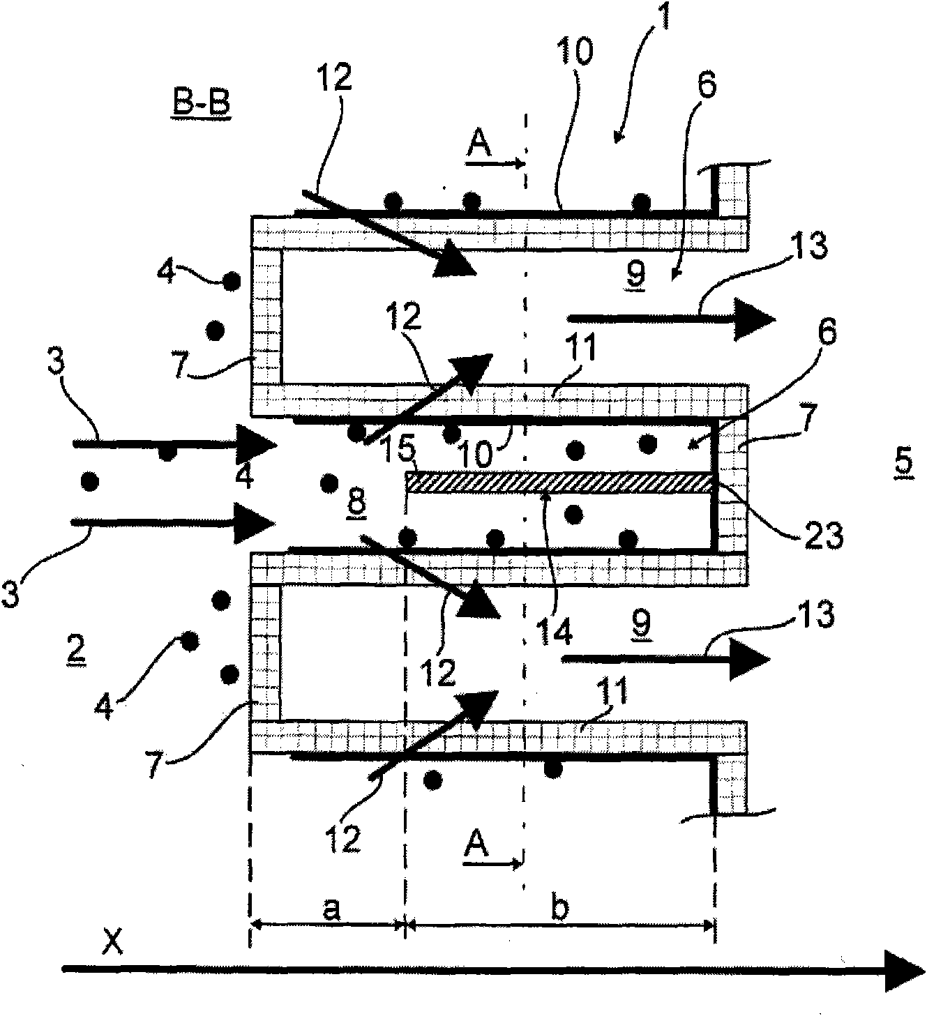
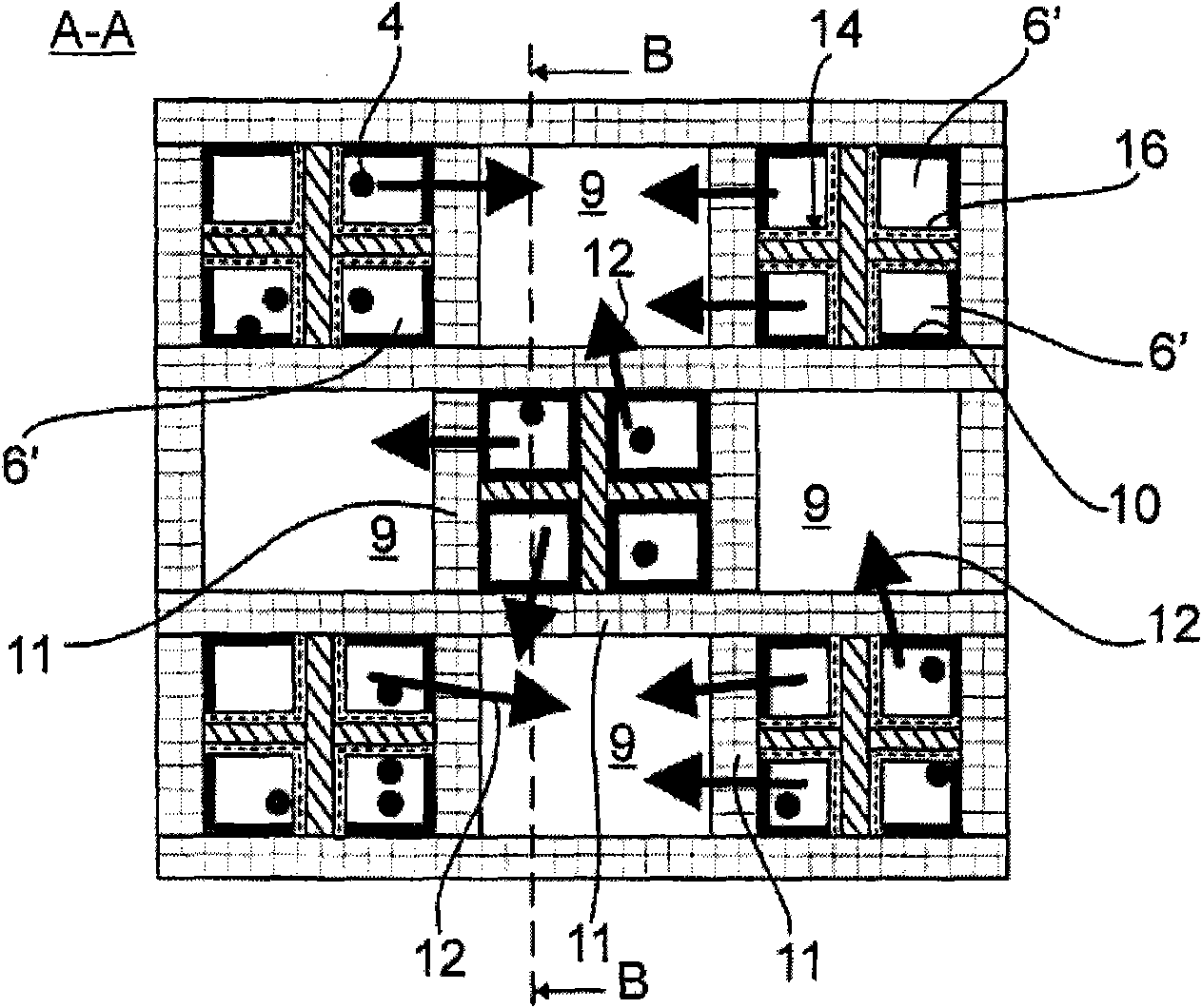
[0037] attached figure 1 Schematically shows a longitudinal section of the particulate filter 1 according to the invention, along the figure 2 The cross-section taken by section line B-B is shown. attached figure 2 shown along the attached figure 1 The cross-section taken by section line A-A is shown.

[0038] The untreated exhaust gas stream 3 entraining a large amount of soot particles 4 to be separated flows on the inflow side 2 to the particle filter 1 .

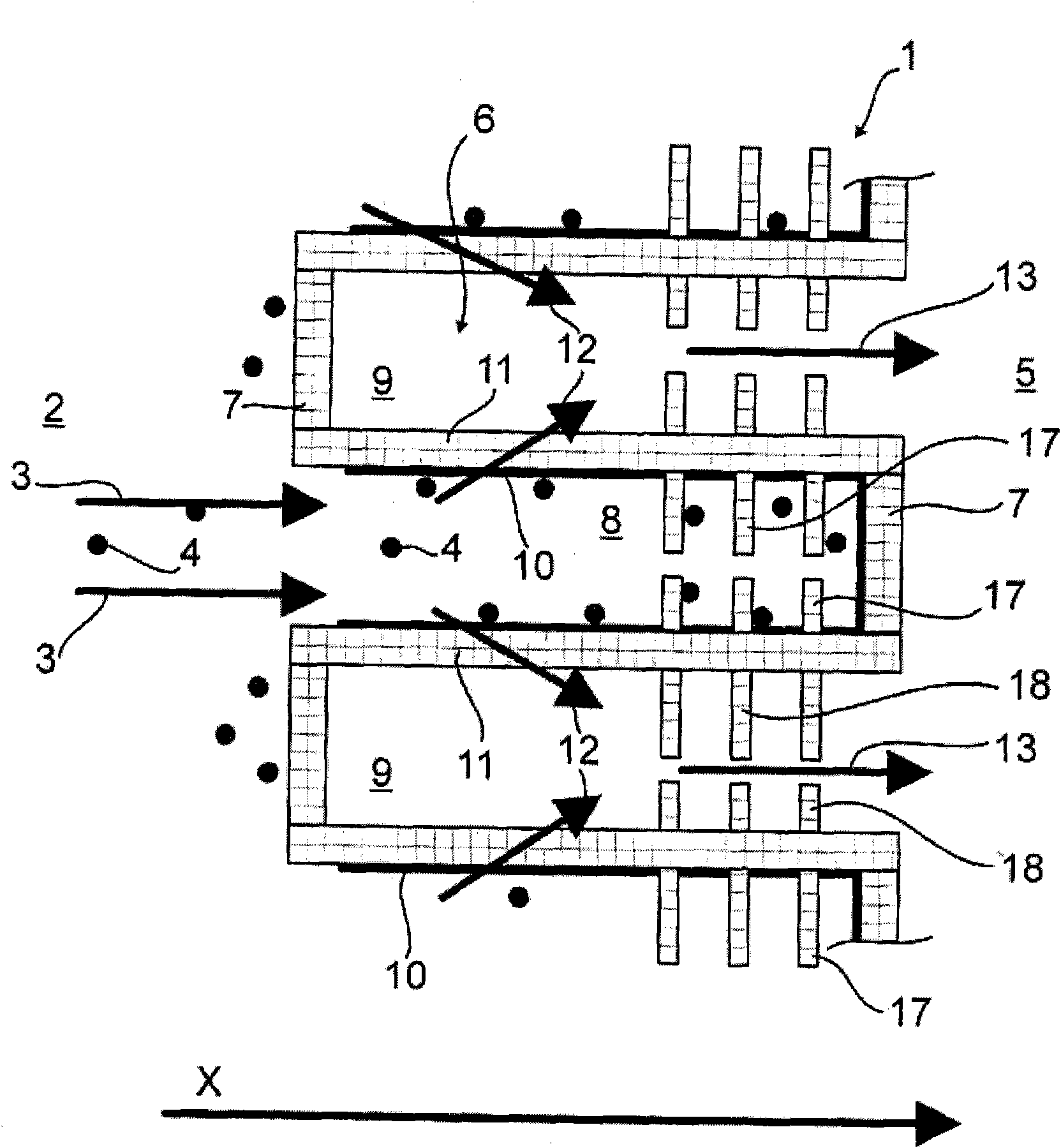
[0039] The particle filter 1 has several parallel flow channels 6 arranged directly next to each other, which channels are closed alternately, as shown, on the inflow side 2 and on the outflow side 5 opposite the main flow direction x with, for example, integrated end walls (Stirnwand) 7, The individual flow channels 6 alternately form a first blind or pocket chamber 8 open towards the inflow side 2 and a second blind or pocket chamber 9 open towards the outflow side 5 . Cordierite, aluminum titanate or silicon ca...


PUM


Abstract

The particle separator (1) has different heat transfer areas (a,b) in terms of heat storage capacity or heat conductivity or heat transfer characteristics of exhaust gas flows (3,12,13) along the mainflow direction (x) of the exhaust gas flow through the particle separator. A defined heat quantity is transferred from the exhaust gas flows (3,12,13) over the respective assigned particle separatorsection.

Description

technical field [0001] The invention relates to a particle separator (Partikelabscheider), in particular a particle filter (Partikelfilter), for separating particles from an exhaust gas flow (Abgastrom) of an internal combustion engine (Brennkraftmaschine) according to the preamble of claim 1 . Background technique [0002] A particle separator according to the invention is, on the one hand, a particle separator whose flow channel diameter is significantly larger than the diameter of the largest exhaust gas particle present. On the other hand, it is also commonly referred to as a particulate separator, whose flow channel diameter is within the particle diameter range of the exhaust gas flow, and / or in which the exhaust gas flow flows through a filter medium. Due to this difference, the particulate filter is at risk of clogging, which increases the exhaust back pressure and reduces the engine power (motorleistung) as the amount of separated soot increases. A known possibilit...

Claims


Application Information

Patent Timeline
Patent Type & Authority Applications(China)
IPC IPC(8): F01N3/023F01N3/28
CPCF01N2510/0682F01N2330/60F01N2330/32F01N2330/38F01N3/0222Y02T10/20Y02T10/22Y02T10/12
Inventor A·多林
Owner MAN TRUCK & BUS AG
Learn More