
Heat radiating fan wheel

A technology of fan wheel and hub, applied in the field of cooling fan wheel, can solve the problem of single, high-frequency sharp noise and so on

Active Publication Date: 2010-03-24
SUNONWEALTH ELECTRIC MACHINE IND
View PDF0 Cites 3 Cited by
  • Summary
  • Abstract
  • Description
  • Claims
  • Application Information

AI Technical Summary

Problems solved by technology

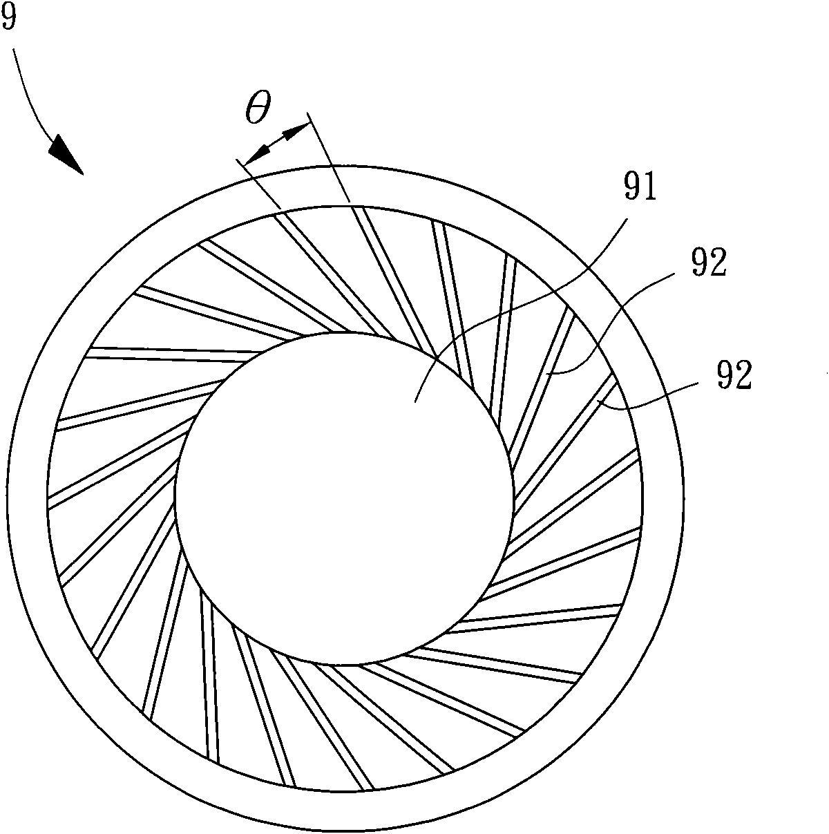
[0003] Generally speaking, since the included angles (θ) between the blades 92 of the existing fan wheel 9 are the same, when the blades 92 of the fan wheel 9 drive the external airflow to perform heat dissipation, the same is likely to occur. Vibration frequency noise (Tone), and further form a single frequency noise through the transmission of air
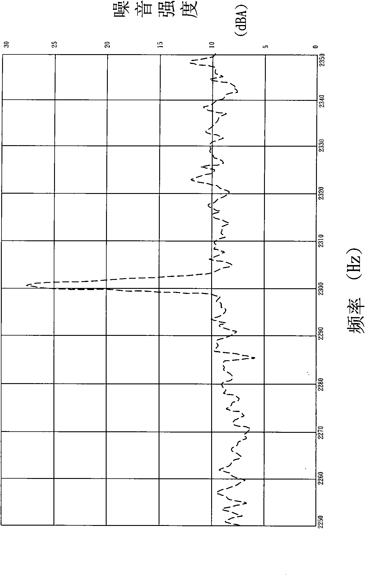
like figure 2 As shown in the experimental test diagram, it can be seen that the existing fan wheel 9 is indeed prone to high-frequency sharp noise at a single frequency, so there is still a need for improvement

Method used


Image

  • Heat radiating fan wheel
  • Heat radiating fan wheel
  • Heat radiating fan wheel

Examples


Embodiment Construction

[0019] In order to make the above-mentioned and other objects, features and advantages of the present invention more comprehensible, the preferred embodiments of the present invention are specifically cited below, together with the accompanying drawings, as follows:

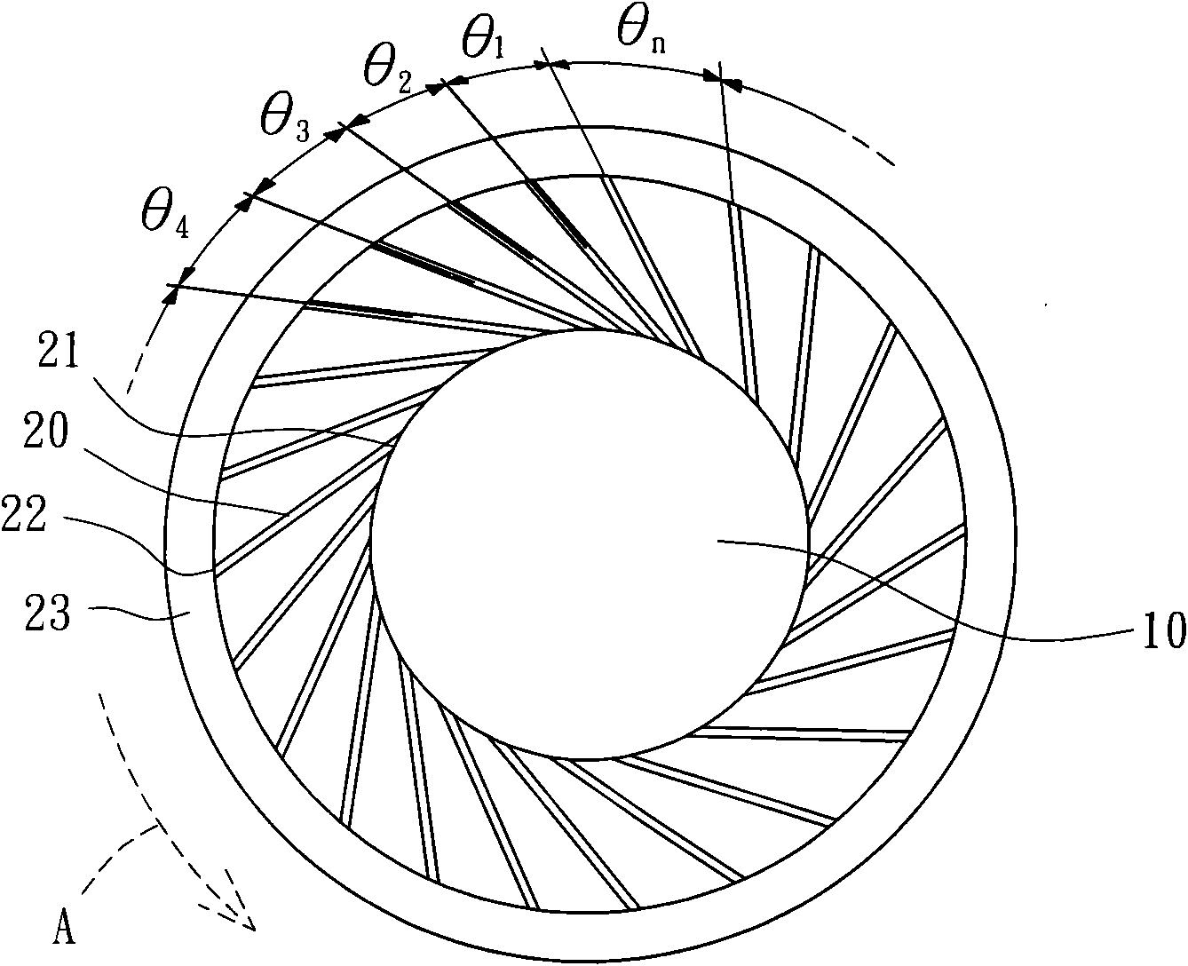
[0020] Please refer to image 3 As shown, the cooling fan wheel of the present invention has a hub 10 and several blades 20 . The hub 10 is mainly installed inside a blower fan frame (not shown), so as to drive the hub 10 to rotate by a stator; each of the blades 20 is radially connected to the outer peripheral surface of the hub 10 in a radial arrangement , and each of the blades 20 has different included angles, so that the included angles of each of the blades are sequentially designed to form incremental angles, thereby effectively reducing the intensity of single-frequency noise generated by the cooling fan wheel. Thereby, when the heat dissipation fan wheel of the present invention drives the external airf...


PUM


Abstract

The invention relates to a heat radiating fan wheel provided with a wheel hub, wherein a plurality of blades are formed on the periphery wall of the wheel hub; the total number of the blades is n; anincluded angle (theta1, theta2, theta3, ..., thetan) is formed between every two adjacent blades; from the included angle (theta1), the heat radiating fan wheel orderly has the included angle (theta2), the included angle (theta3), ..., the included angle (thetan) in the clockwise or counterclockwise direction; and the included angles of the blades can orderly form the design of increment angles, so that the included angles of the blades are different. Thus, when the fan wheel drives the external air flows to carry out the heat radiation, noises with the same vibration frequency are not easilyproduced.

Description

technical field [0001] The invention relates to a fan wheel, in particular to a cooling fan wheel of a blower fan. Background technique [0002] Please refer to figure 1 As shown, the fan wheel 9 of the existing blower fan has a hub 91, the outer peripheral wall of the hub 91 is formed with several blades 92, and each of the blades 92 has an included angle (θ) between each other, and each of the included angles (θ) are exactly the same angle. Thereby, the fan wheel 9 can be installed inside a fan frame (not shown), and the fan wheel 9 can be driven to rotate by a stator (not shown), so that the fan wheel 9 can be introduced External airflow, and drive the external airflow for heat dissipation. [0003] Generally speaking, since the included angles (θ) between the blades 92 of the existing fan wheel 9 are the same, when the blades 92 of the fan wheel 9 drive the external airflow to perform heat dissipation, the same is likely to occur. The noise (Tone) of the vibration fr...

Claims


Application Information

Patent Timeline
IPC IPC(8): F04D29/30F04D29/38
Inventor 洪银树卢加达陈建宏
Owner SUNONWEALTH ELECTRIC MACHINE IND
Learn More