Temperature-uniforming plate

A technology of vapor chamber and bottom plate, which is used in lighting and heating equipment, indirect heat exchangers, cooling/ventilation/heating renovation, etc. Welding and assembly problems

Active Publication Date: 2010-03-24
PEGATRON
View PDF8 Cites 8 Cited by
  • Summary
  • Abstract
  • Description
  • Claims
  • Application Information

AI Technical Summary

Problems solved by technology

However, the excessively long circulation path and the small capillary structure permeability (permeability) will generate a large flow resistance, thereby reducing the heat transfer capacity of the chamber A1
Furthermore, the mechanical strength of this vapor chamber A1 is relatively weak and cannot withstand the internal water vapor pressure (about 4.7atm) at a temperature of 150°C, so it is not conducive to the soldering assembly of the heat dissipation module

Method used


Image

  • Temperature-uniforming plate
  • Temperature-uniforming plate
  • Temperature-uniforming plate

Examples


Embodiment Construction

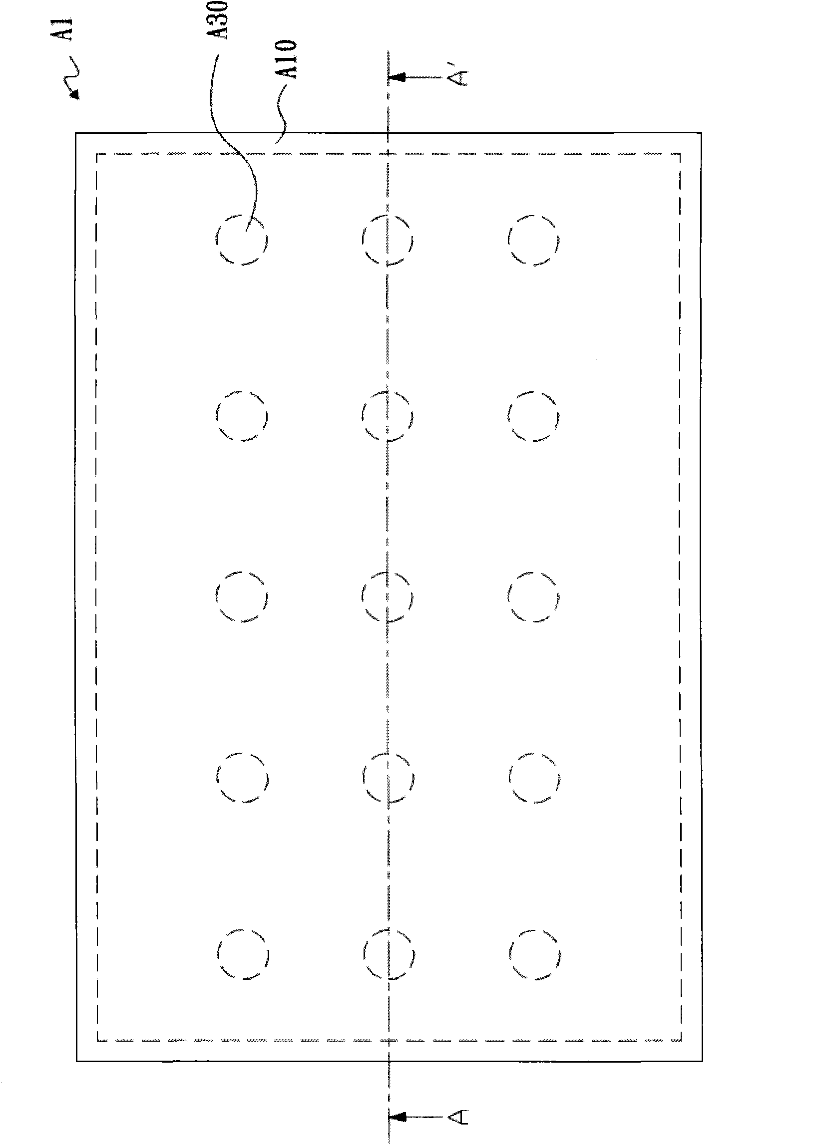
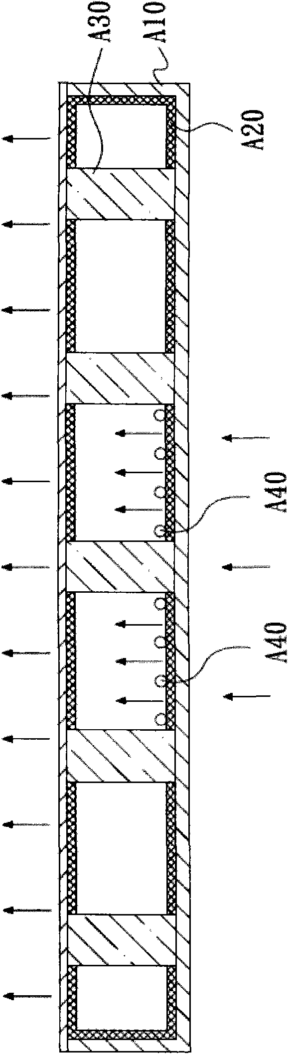
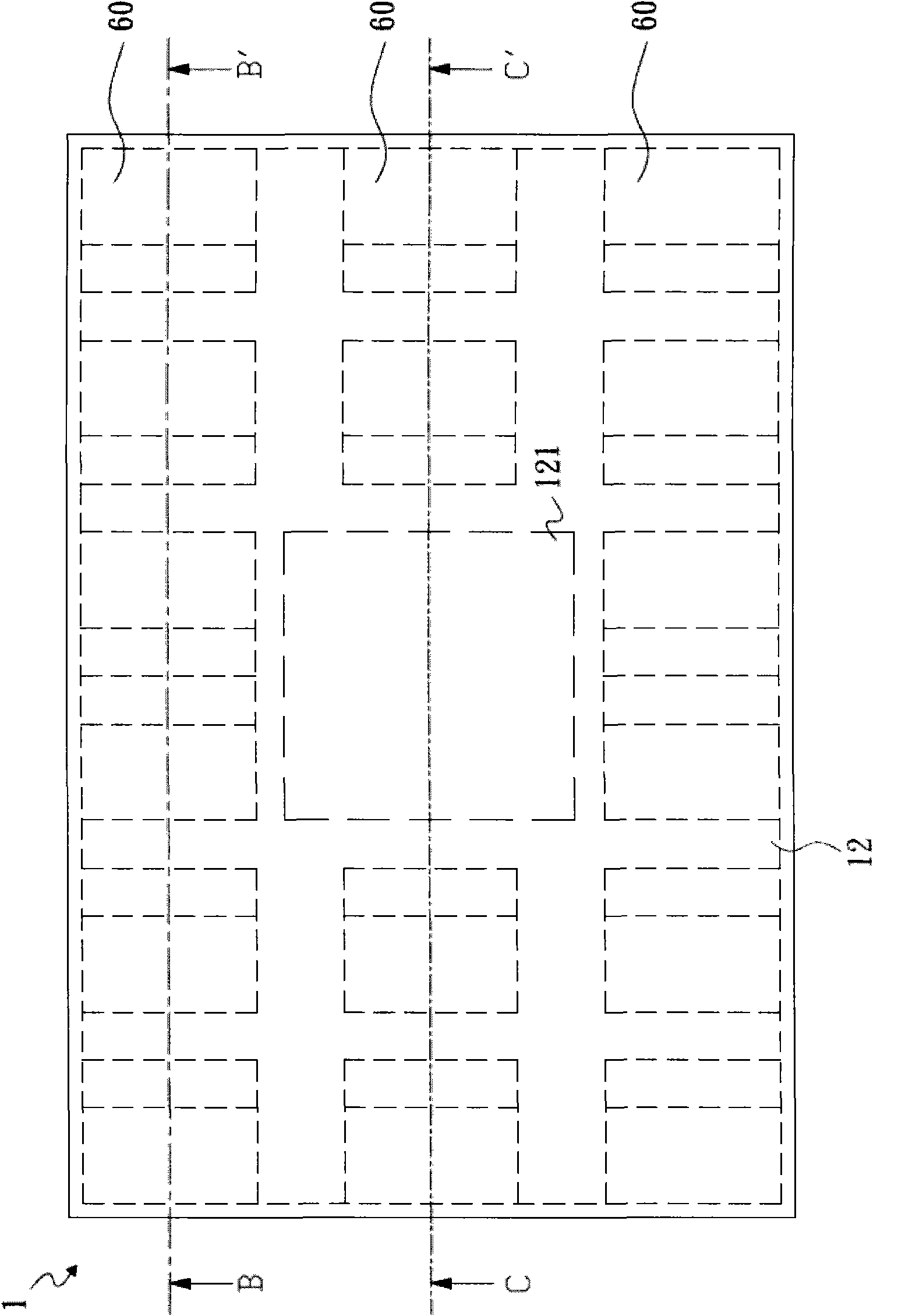
[0021] see image 3 , Figure 4 and Figure 5 As shown, it is the vapor chamber disclosed in the first embodiment of the present invention. The vapor chamber 1 includes a vacuum cavity 10 , a working fluid 20 , an upper capillary structure 30 , a lower capillary structure 40 , and a plurality of support columns 60 .

[0022] The vacuum chamber 10 has a roughly rectangular shape and is composed of an upper cover 11 and a bottom plate 12 . The sides of the bottom plate 12 are bent and welded to the upper cover 11 at high temperature to form a closed space between the upper cover 11 and the bottom plate 12 . In addition, the bottom plate 12 is provided with a heating area 121 at the center, and the upper cover 11 is provided with a cooling area 111 corresponding to the heating area 121 .

[0023] The working fluid 20 is located in the vacuum cavity 10 , and it is a fluid with two phase changes, preferably water, but the invention is not limited thereto.

[0024] The upper capi...


PUM


Abstract

The invention relates to a temperature-uniforming plate, comprising a vacuum cavity, a working fluid, a lower capillary structure and a plurality of support pillars, wherein the vacuum cavity comprises an upper cover and a bottom plate and is filled with a proper amount of working fluid; the lower capillary structure is arranged on the bottom plate; the support pillars are positioned in the vacuumcavity and are connected with the upper cover and the bottom plate to support the upper cover; a first inclined angle is formed between each support pillar and the upper cover; and after being condensed, the vaporous working fluid flows back to the bottom plate through the support pillars from the upper cover.

Description

technical field [0001] The invention relates to a uniform temperature plate, in particular to a uniform temperature plate with enhanced heat transfer capability. Background technique [0002] With the development and progress of information technology, the size of semiconductor power crystals (such as CPU, GPU, high-power LED) is getting smaller and smaller, the heat generated by power crystals is getting higher and higher, and the heat flux per unit area is getting bigger and bigger. Operate under the allowable temperature, and combine various forms of heat sinks on the electronic components to provide heat dissipation. Among them, the vapor chamber has the advantages of high thermal conductivity, high heat transfer capacity, simple structure, light weight, and no power consumption. It is very suitable for the heat dissipation requirements of electronic components, and its application will become more and more popular. [0003] Such as figure 1 and figure 2 As shown, th...

Claims


Application Information

Patent Timeline
Patent Type & Authority Applications(China)
IPC IPC(8): F28D15/02H05K7/20
Inventor 刘睿凯张育玮锺兆才
Owner PEGATRON
Why Eureka
Try Eureka