Vehicular heating system

A technology for heating systems and vehicles, applied to vehicle seats, vehicle parts, heating/cooling equipment, etc., which can solve the problem of not being able to fully heat seat heaters and planar electric heaters independently

Active Publication Date: 2010-03-24
PANASONIC CORP
View PDF9 Cites 10 Cited by
  • Summary
  • Abstract
  • Description
  • Claims
  • Application Information

AI Technical Summary

Problems solved by technology

[0003] However, in the prior art, a seat heater composed of a flexible planar heating element installed under the skin of the seat cushion and the seat back and a planar electric heater installed along the surface of the inner member are u...

Method used


Image

  • Vehicular heating system
  • Vehicular heating system
  • Vehicular heating system

Examples


no. 1 example

will be passed by reference Figure 1 to Figure 2 A first embodiment of the present invention will be described.

[0011]

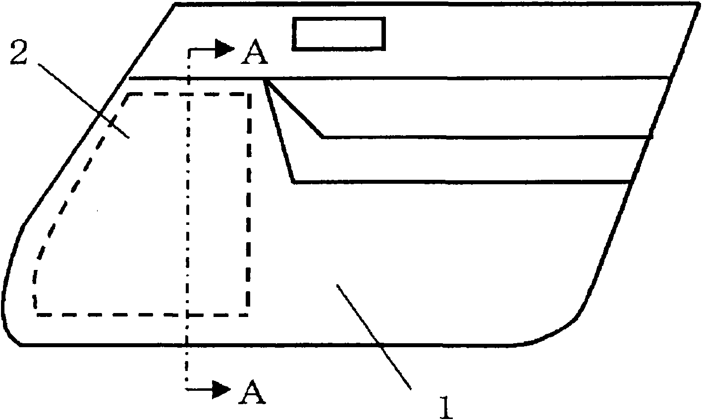
figure 1 is an external view of the side door panel 1 including the vehicle heating system according to the first embodiment of the present invention. Here, the side door panel 1 is a side door for a driver's seat side of a right-hand drive vehicle. In the drawings, a heating device 2 is installed in a side door panel 1 as an interior member. The heating device 2 is such that an extremely thin heating wire is meandered on a sheet of nonwoven fabric so as to be formed into a sheet shape. The thermistor is installed near the heating wire. In addition, although not shown, a control device is provided which controls the energization of the heating wire so that the output of the thermistor becomes a preset set temperature.

[0012] figure 2 is shown along the figure 1 A diagram of the configuration of a vehicle heating system in cross-section obtained i...

no. 2 example

will refer to image 3 A second embodiment of the present invention will be described.

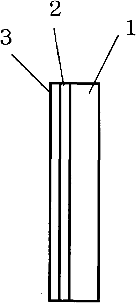
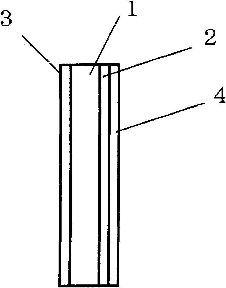
[0019] image 3 is shown along with figure 1 The cross-section obtained in line A-A corresponds to the cross-section in the diagram of the construction of this embodiment. In this example, if image 3 As shown in , the heating device 2 is installed on the outer side of the side door panel 1, and the heat radiation member 3 is installed on the inner side thereof. In addition, a heat insulating member 4 is installed on the outer surface of the heating device 2 . As the side door panel 1 in this embodiment, a material having good thermal conductivity, for example, a composite material in which metal particles are mixed with resin, is used at least for the area where the heating device 2 is installed.

[0020] Heat generated in the heating device 2 is efficiently conducted to the heat radiation member 3 through the heat insulating member 4 and the side door panel 1 having good thermal cond...

no. 3 example

will be passed by reference Figure 4 A third embodiment of the present invention will be described.

[0022] Figure 4 is to show the construction of this embodiment and along with figure 1 The line A-A in the figure corresponds to the cross-section obtained. In this example, if Figure 4 As shown in , the heating device 2 is installed in the side door panel 1 , and a cover 5 is provided which covers the heating device 2 and transmits heat radiation generated from the heating device 2 . When facing the drawings, the left-hand side represents the inside of the vehicle, and the right-hand side represents the outside of the vehicle.

[0023] The cover 5 includes a void portion 6 between the heating device 2 and itself, and the covering surface of the cover 5 has a mesh member 6 having a predetermined opening ratio. The void portion 6 is formed by providing a spacer or the like between the heating device 2 and the mesh member 7 . The mesh member 7 is constituted by, for exam...


PUM


Abstract

When a seat heater and a planar electric heater on a surface of an interior member are used in parallel, the seat heater and the planar electric heater cannot be heated sufficiently due to a limitation on an electric capacity of a vehicle, and in particular, in a vehicle having good engine efficiency, heating of an interior of a passenger compartment by air conditioning utilizing hot air generatedby heat expelled from an engine is not sufficient, whereby there sometimes occurs a situation where occupants feel cold. A heating device 2 is provided in a side door panel 1 of a vehicle and a seatheater is made to be heated mainly at an initial stage of heating after an occupant gets in the vehicle, whereas the heating device 2 is made to be heated after a predetermined period of time elapses,whereby the body of the occupant can be warmed quickly and efficiently without making the occupant feel cold physically.

Description

technical field [0001] The present invention relates to heating systems. Background technique [0002] Conventionally, Patent Document 1 discloses a vehicle heating system of this type. In this prior art, a planar electric heater is provided along the surface of an interior member in a vehicle compartment, and on the surface of the electric heater is provided a Heat radiation components made of materials with high thermal emissivity coefficient. Then, the heat radiation member is heated by the heat generated by the electric heater, so that infrared radiation is radiated from the surface of the heat radiation member. Patent Document 1: JP-A-2005-212556 Contents of the invention The problem to be solved by the present invention [0003] However, in the prior art, a seat heater composed of a flexible planar heating element installed under the skin of the seat cushion and the seat back and a planar electric heater installed along the surface of the inner member are used a...

Claims


Application Information

Patent Timeline
IPC IPC(8): B60H1/22A47C7/74B60H1/00
CPCB60N2/5685B60H1/00271B60H2001/2293B60H1/2218B60H1/00285B60H1/2225B60H1/2226B60H1/2227
Inventor 荻野弘之米野范幸小西英昭朝见直仁有马聪
Owner PANASONIC CORP
Why Eureka
Try Eureka