
Power transmission device

A power transmission device and power technology, which is applied in the direction of power device, pneumatic power device, transmission device, etc., can solve the problems of increasing the distance between the number of shafts and increasing the weight, and achieve the purpose of preventing the temporary decrease of torque and making the structure small. The effect of reducing and suppressing the speed change

Active Publication Date: 2010-03-24
TOYOTA JIDOSHA KK
View PDF13 Cites 29 Cited by
  • Summary
  • Abstract
  • Description
  • Claims
  • Application Information

AI Technical Summary

Problems solved by technology

[0006] However, the devices or systems described in the above-mentioned patent publications have a structure for selectively distributing the torque of the engine to two clutch shafts, and in addition, a differential electric motor is arranged at right angles between these clutch shafts via bevel gears. The structure of the generator, so the number of shafts increases or the distance between the shafts becomes larger, and the overall structure may be enlarged and the weight may increase

Method used


Image

  • Power transmission device
  • Power transmission device
  • Power transmission device

Examples


Embodiment Construction

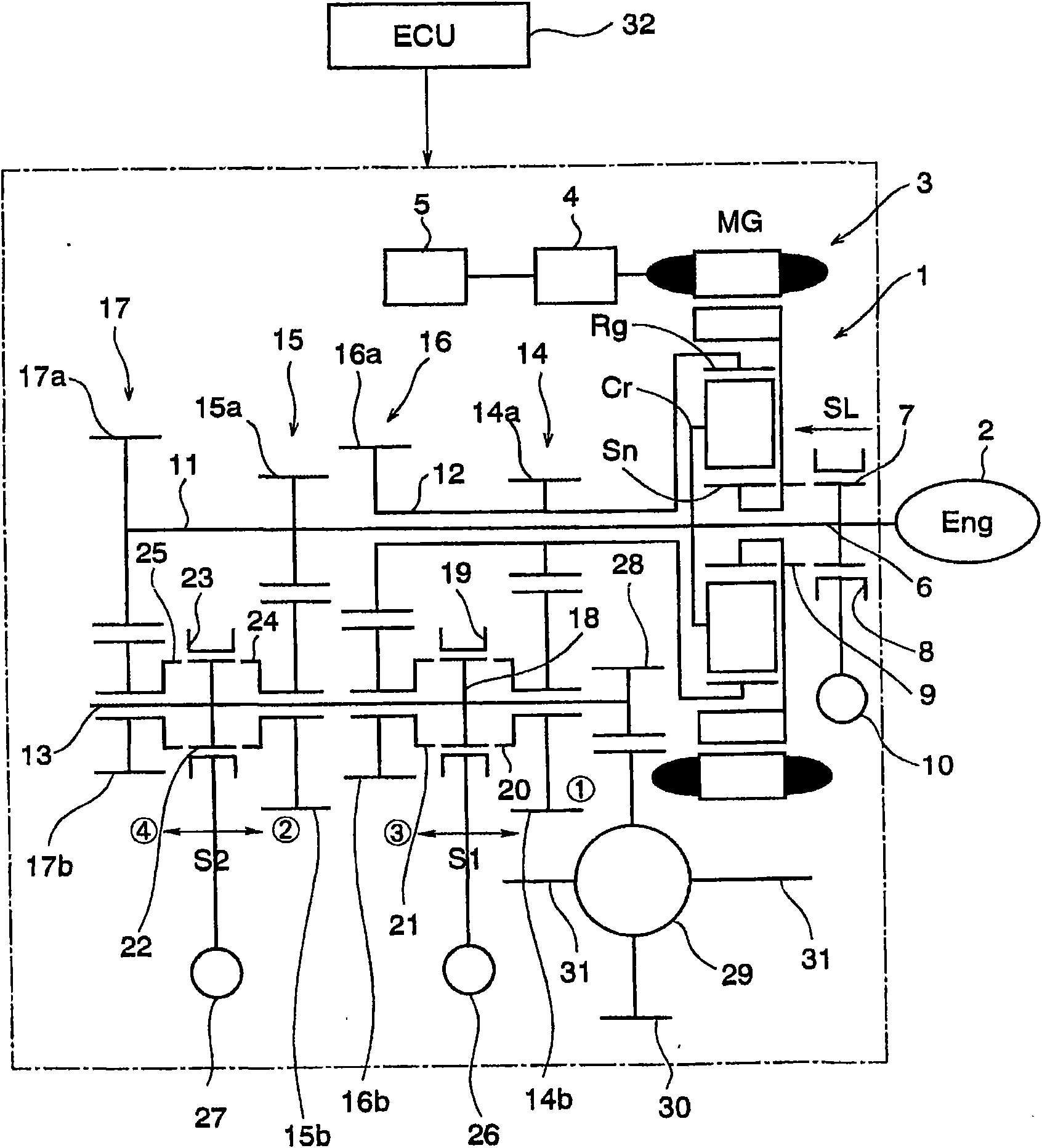
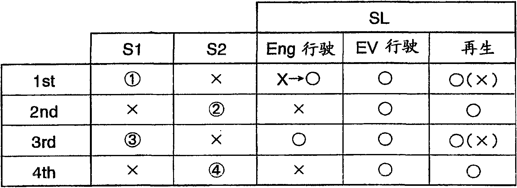
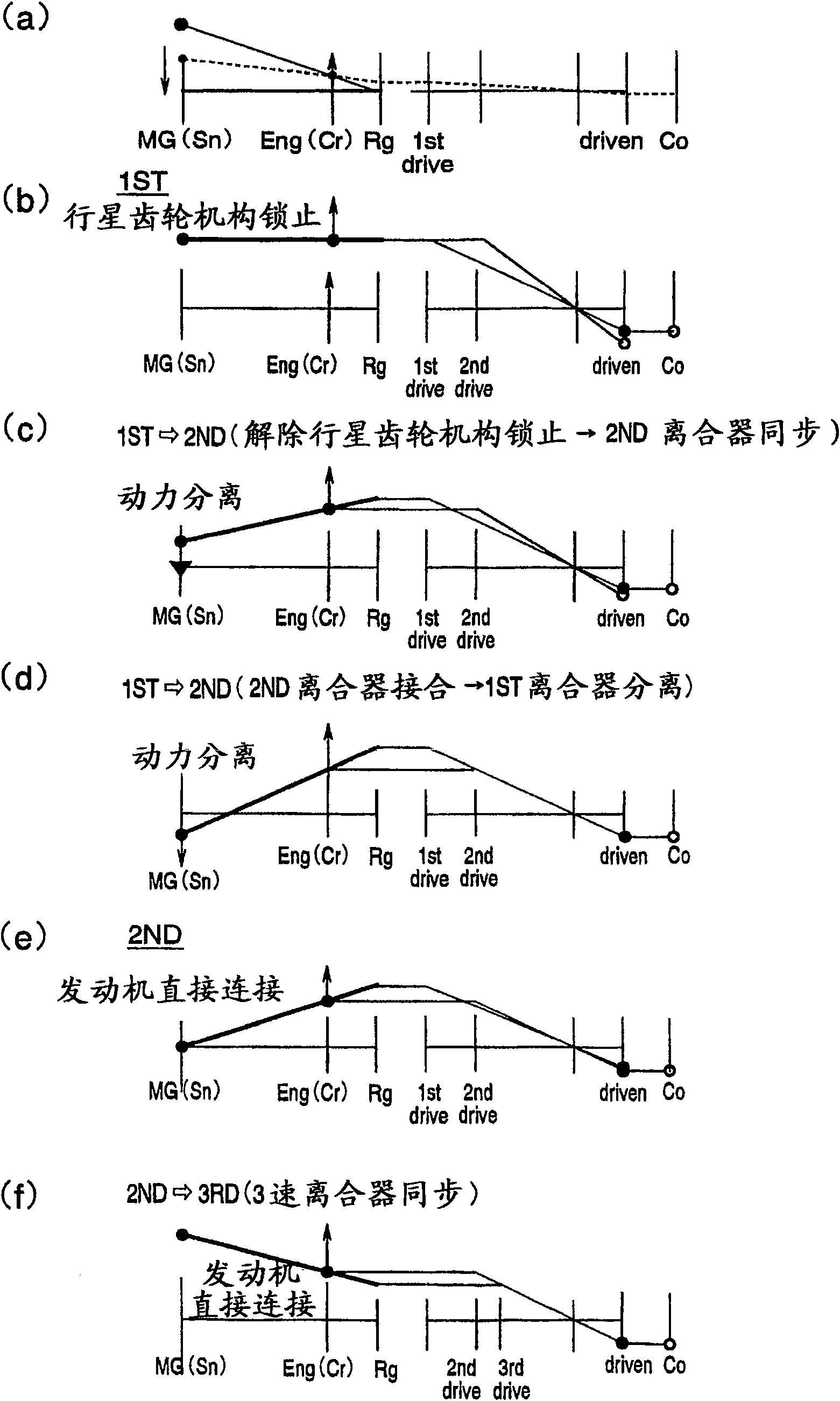
[0061] Next, the present invention will be described more specifically. The power transmission device of the present invention is basically configured to transmit power output from an engine to an output member via a transmission gear pair selected from a plurality of transmission gear pairs having different gear ratios, and output power from the output member. The engine is mainly a power source, and an internal combustion engine such as a gasoline engine or a diesel engine is a typical example, but it is not limited thereto, and may be other power devices such as an electric motor. In addition, the transmission gear pair is a gear pair composed of a driving gear and a driven gear (driven gear) that are constantly meshing with each other, and can be a gear pair used in a manual transmission for a conventional vehicle, a dual-clutch transmission, etc. same structure. In addition, the number of the transmission gear pairs may be plural, and the greater the number, the greater ...


PUM


Abstract

A power transmission device that has reduced power loss and is downsized so that it can be more easily mounted on a vehicle. The power transmission device includes an engine (2), transmission gear pairs (14-17) having different gear ratios and to which power outputted from the engine (2) is selectively transmitted, and an output member (11) for outputting power transmitted from any selected one of the transmission gear pairs (14-17). The power transmission device further includes a differential mechanism (1) having three rotation elements for performing differential action, the three rotation elements including a first rotation element to which the engine (2) is connected, and also includes an electric motor (3) connected to a second rotation element of the three rotation elements. The transmission gear pairs (14-17) include first transmission gear pairs (14, 16) connected to the first rotation element and to the output member (11) and also include second transmission gear pairs (15, 17) connected to a third rotation element of the three rotation elements and to the output member.

Description

technical field [0001] The present invention relates to a power transmission device for transmitting power output from a power source such as an engine or a motor to an output member such as an output shaft or an output gear, and particularly relates to a power transmission device capable of changing the ratio of the rotational speed of the power source to the rotational speed of the output member . Background technique [0002] This type of power transmission device is widely used to vary the output torque according to requirements, or to control the rotational speed of a power source to a rotational speed with high efficiency. Mechanisms having a plurality of gear pairs are often used as mechanisms having a function of changing torque and rotational speed. In addition, when a gear pair is used, power transmission efficiency can be improved compared to a mechanism using a belt, chain, or fluid. [0003] This example is described in Japanese Unexamined Patent Publication N...

Claims


Application Information

Patent Timeline
IPC IPC(8): B60K6/365B60K6/40B60K6/48B60K6/547F16H3/083B60K6/445B60K6/485B60K17/04B60W10/10B60W10/18B60W20/00F16H3/72F16H59/14F16H59/46F16H59/74F16H61/02F16H61/68F16H61/684F16H61/688F16H63/50
CPCF16H3/006B60K6/365F16H2003/0818B60K6/547F16H3/126B60W10/11F16H2200/0052B60K6/40F16H2003/0931F16H2200/0047F16H2200/0043B60W20/00B60K2006/541Y02T10/6221B60W10/02B60K6/48F16H3/725B60L3/003B60L3/0061B60L7/14B60L15/2009B60L15/2054B60L2210/40B60L2220/14B60L2240/12B60L2240/421B60L2240/423B60L2240/425B60L2240/441B60L2240/443B60L2240/525B60L2240/545B60L2260/26B60L2270/145B60L50/16Y02T10/62Y02T10/64Y02T10/72Y02T10/7072B60W20/30B60L3/0046Y02T10/70
Inventor 出盐幸彦驹田英明太田隆史
Owner TOYOTA JIDOSHA KK
Learn More