Driver brake control method without using external brake unit

A braking control and braking unit technology, which is applied in the direction of motor generator control, electromechanical brake control, electronic commutation motor control, etc., can solve the problems of long energy duration, affecting the control effect of the driver, affecting the braking effect, etc.

Active Publication Date: 2021-08-20
赵炫弟
View PDF11 Cites 0 Cited by
  • Summary
  • Abstract
  • Description
  • Claims
  • Application Information

AI Technical Summary

Problems solved by technology

The impact of this method is too large, and it is mostly used in special motor occasions
[0007] All of the above methods are consuming and accumulating excessive energy. If the energy density is too large, or the energy duration is too long, the braking effect will be affected in the slightest, and the related equipment will be damaged in severe cases.
On the other hand, the traditional AC motor control mode uses a built-in / external brake unit or an energy feedback unit to control the bus voltage. When the motor enters the energy feeding state, the control system only focuses on the adjustment of the DC bus voltage. There are the following problems: the energy control method is single, or the control right on the DC bus side of the energy feedback mode is completely given up, causing the control system to passively accept the current state, but not to adjust the drive in a timely manner according to the state of the drive, which greatly affects the control of the drive Effect

Method used


Image

  • Driver brake control method without using external brake unit
  • Driver brake control method without using external brake unit
  • Driver brake control method without using external brake unit

Examples


Embodiment Construction

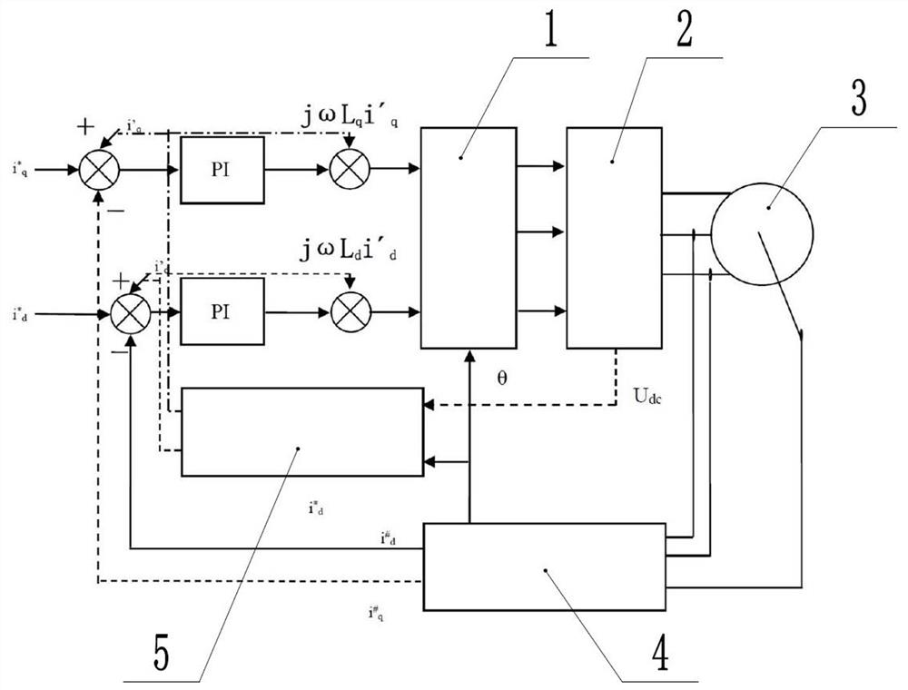
[0022] The technical scheme of the present invention is described in detail below in conjunction with accompanying drawing:

[0023] Such as figure 1 , a braking control method for a driver without using an external braking unit, the driver includes a control module 1 , a first detection module 2 , a second detection module 4 and an adjustment module 5 . The first detection module 2 is used to monitor the bus voltage, the second detection module 4 includes a rotor magnetic field observer, and the rotor magnetic field observer includes a position detection device, a voltage sensor, a current sensor and a speed sensor, and the position detection The device is used to monitor the rotor position, the voltage sensor is used to monitor the input voltage of the motor 3, the current sensor is used to monitor the input current of the motor 3, and the rotor position, input voltage and input current are used to determine the direction of the rotor magnetic field . The speed sensor is u...


PUM


Abstract

The invention discloses a driver brake control method without using an external brake unit. The method comprises the steps of determining the size and direction of a motor rotor magnetic field through a rotor magnetic field observer of a driver, and by taking the size and direction of the motor rotor magnetic field as a basis, controlling the size and the direction of the stator magnetic field by adjusting the size and the direction of the d-axis current injected from the stator side, thereby controlling the operation magnetic field of the motor, enabling the reverse electromotive force voltage not to exceed the input voltage of the motor, and preventing the motor from entering a power generation state. According to the method, the amplitude of converting mechanical energy into electric energy is controlled by changing the field intensity of the magnetic field of the motor, the rotating speed change of the motor is restrained, and the whole-course controllable implementation strategy of motor braking is achieved; and the energy of the motor is always in a controllable state, so that the speed reduction of the motor and the pumping of the voltage of the direct current bus are controlled by the driver, and the protection of the motor and related parts of the driver is better realized.

Description

technical field [0001] The invention relates to the technical field of motor brake control, in particular to a driver brake control method without an external brake unit. Background technique [0002] In the frequency conversion speed regulation system, the speed of the AC synchronous motor and the AC asynchronous motor changes according to the change of the control frequency. When the motor needs to decelerate, the driving frequency first decreases, and the motor starts to brake and decelerate. Due to the mechanical inertia, the motor enters the power generation state from the electric state at the moment of deceleration. The free stop of the AC asynchronous motor occurs when the excitation current completely disappears. At this time, the system does not have the power generation state. In addition, the power generation of the motor in other cases depends on the target frequency of the controller and the speed frequency of the motor rotor. The difference between them, the ...

Claims


Application Information

Patent Timeline
IPC IPC(8): H02P21/10H02P21/36
CPCH02P21/10H02P21/36Y02T10/72
Inventor 赵炫弟宋岽栋
Owner 赵炫弟
Why Eureka
Try Eureka