Balancing shaft

A technology for balancing shafts and balancing weights, applied in the field of balancing shafts, can solve problems such as the reduction of motion quality, and achieve the effect of improving operation stability and smooth operation.

Active Publication Date: 2010-03-24
HERZOG INTERTEC GMBH
View PDF1 Cites 9 Cited by
  • Summary
  • Abstract
  • Description
  • Claims
  • Application Information

AI Technical Summary

Problems solved by technology

Such a balance shaft is partly constructed weight-optimized, but requires a further reduction of the moving mass due to the higher rotational speeds in multi-cylinder engines

Method used


Image

  • Balancing shaft
  • Balancing shaft
  • Balancing shaft

Examples


Embodiment Construction

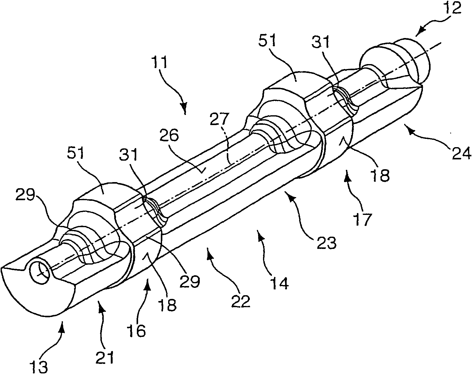
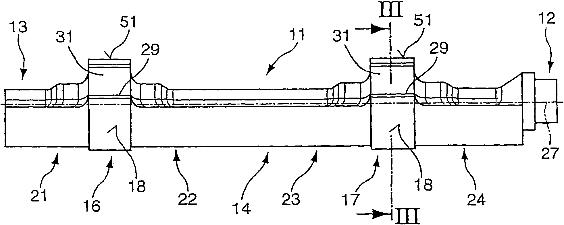
[0044] figure 1 A first embodiment of the balancing shaft 11 according to the invention is shown in perspective in the middle. Such a balancing shaft 11 is provided, for example, for a multi-cylinder engine and serves to balance second-order inertial forces. Usually two balancing shafts are arranged offset relative to each other, which then rotate counter to each other at double the engine speed.

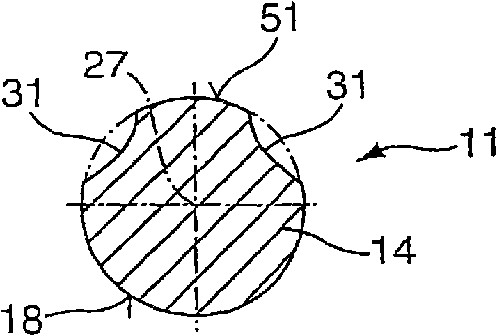
[0045] exist figure 1 On the rear end section 12 shown in , the balancing shaft 11 is provided with a drive (not shown in detail), for example a sprocket, which drives the balancing shaft 11 . This end section 12 can form a fixed bearing for the balancing shaft 11 . The balancing shaft 11 comprises a base body 14 on which first and second bearing points 16 , 17 are arranged. These bearing points serve to support the balancing shaft 11 in the engine block. The bearing points 16 , 17 have a running surface 18 whose boundary length is designed to be greater than the boundary lengt...


PUM


Abstract

The invention relates to a balancing shaft for a single- or multi-cylinder motor having at least one unbalanced weight section (21, 22; 23, 24) and at least one bearing point (16, 17), wherein the at least one unbalanced weight section (21, 22; 23, 24) is allocated to the bearing point (16, 17) and the bearing point has a radial contact surface (18) that extends only partially over a circumference of the bearing point (16, 17) and a centrifugal force resulting from the rotation of the balancing shaft (11) lies inside a region of the bearing point (16, 17) formed by the contact surface (18) extending partially over the circumference of the bearing point (16, 17), wherein at least one support surface (51) is provided that is provided partially over the circumference of the bearing point (16, 17) and separately from the contact surface (18).

Description

technical field [0001] The invention relates to a balance shaft according to the preamble of claim 1 for a single-cylinder engine or a multi-cylinder engine. Background technique [0002] A balancing shaft for a multi-cylinder engine is known from WO 2005 / 093286 A1, which comprises at least two unbalanced weight sections and at least one bearing point, wherein the unbalanced weight sections are arranged symmetrically with respect to the bearing point Furthermore, at least one of the unbalanced weight sections has an end facing away from the bearing point as a drivable end for the balancing shaft. A flexurally elastic coupling element is arranged between two bearing points with unbalanced weight sections arranged symmetrically thereto in order to connect the two sections to one another. The unbalanced weight section is approximately semicircular in shape. The bearing point is provided as a cylindrical disk, one half of the cylindrically configured bearing point protruding f...

Claims


Application Information

Patent Timeline
Patent Type & Authority Applications(China)
IPC IPC(8): F16F15/26
CPCF16F15/264F16C3/02F16C17/02F16C19/46F16C33/581F16C2361/53Y10T74/2157Y10T74/2183
Inventor E·赫尔左克R·赫尔左克
Owner HERZOG INTERTEC GMBH
Why Eureka
Try Eureka