Articulated robot for laser ultrasonic inspection

An ultrasonic and robotic technology, applied in the direction of material analysis, instruments, and manipulators using sonic/ultrasonic/infrasonic waves, which can solve problems such as increasing the initial total cost of laser ultrasonic testing systems, maintenance costs, inability to test the assembly structure, and discomfort.

Inactive Publication Date: 2010-03-24
LOCKHEED MARTIN CORP
View PDF8 Cites 17 Cited by
  • Summary
  • Abstract
  • Description
  • Claims
  • Application Information

AI Technical Summary

Problems solved by technology

Therefore these architectures are not suitable for use in any type of in-service, remote or field-deployed portable laser ultrasonic flaw detection system
Additionally, because they are so large and heavy, these architectures require robust robotic grippers and complex beam delivery systems, all of which add significantly to the init

Method used


Image

  • Articulated robot for laser ultrasonic inspection
  • Articulated robot for laser ultrasonic inspection
  • Articulated robot for laser ultrasonic inspection

Examples


Embodiment Construction

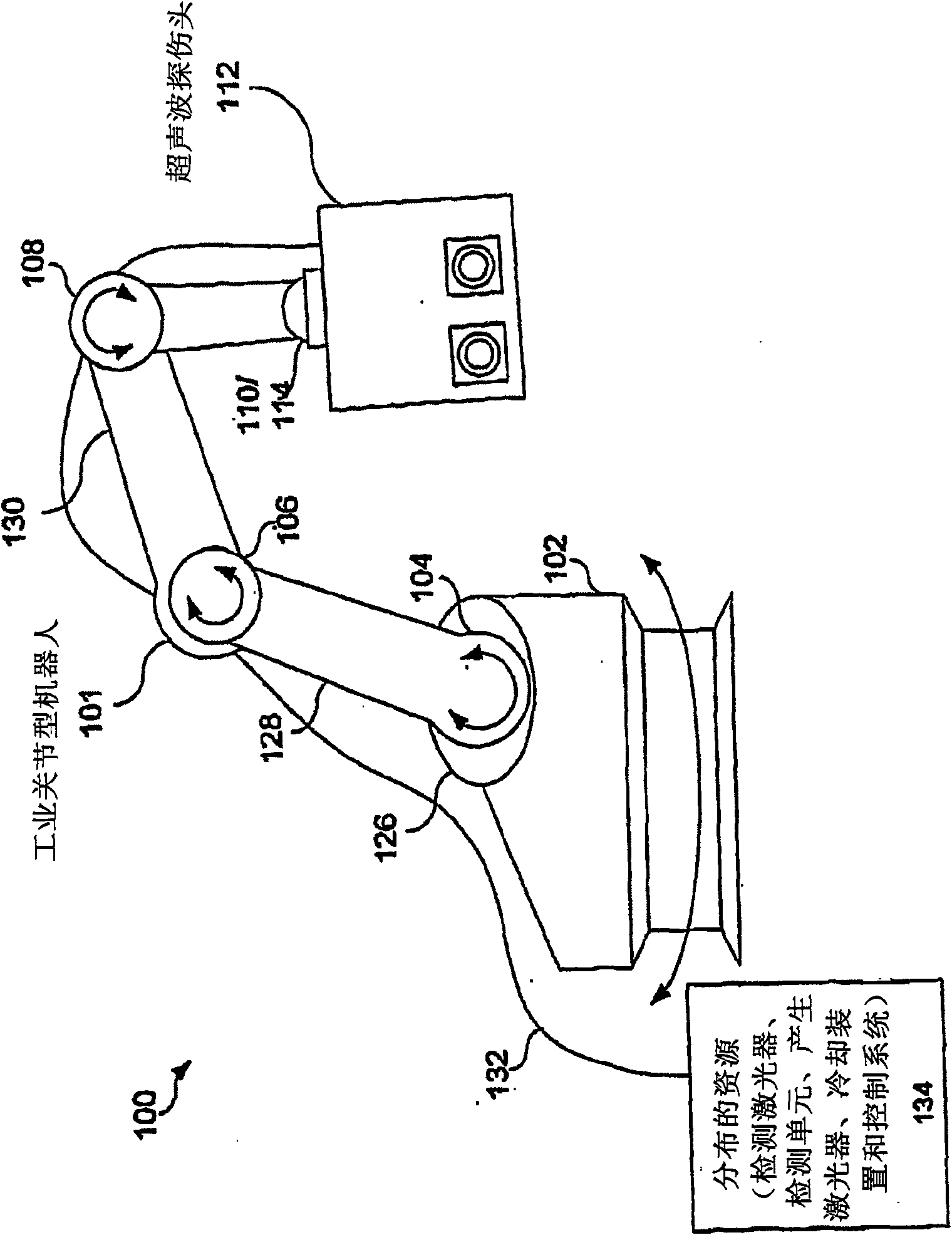
[0031] Preferred embodiments of the invention are depicted in the drawings, like numerals being used to designate like and corresponding parts in the different drawings.

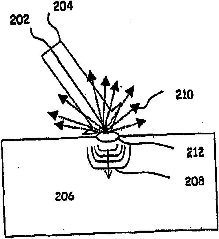
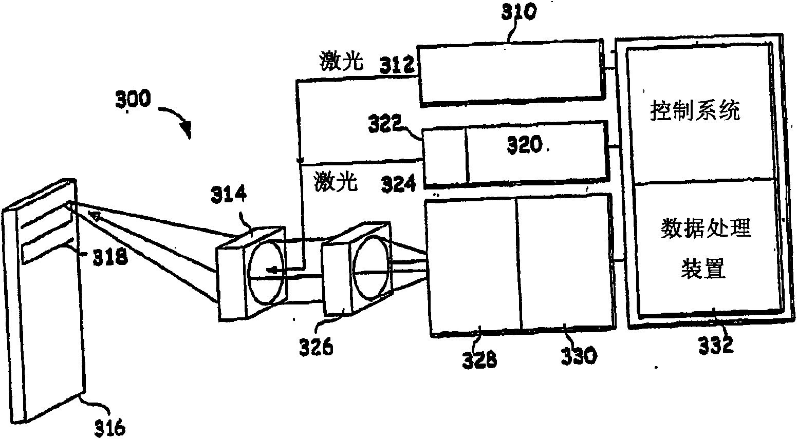
[0032] Laser ultrasonic flaw detection has proven to be a cost-effective tool for non-destructive evaluation (NDE) of polymer-matrix composites. With the increasing use of these composite materials in different industries, the number and complexity of composite parts is increasing. In addition, the installed base of composites is increasing. As objects made of composite materials increase in size and complexity, it becomes increasingly difficult to position laser ultrasonic sensors relative to the surface being inspected. Embodiments of the invention disclosed herein propose a solution to this problem.

[0033] One embodiment places a laser ultrasonic sensor (ie, a laser ultrasonic head) at the end of an articulated robot. Laser ultrasonic flaw detection is typically performed by moving the laser ultrasonic...


PUM


Abstract

An ultrasonic non-destructive evaluation (NDE) system operable to inspect target materials is provided. This ultrasonic NDE system includes an articulated robot, an ultrasound inspection head, a processing module, and a control module. The ultrasound inspection head couples to or mounts on the articulated robot. The ultrasound inspection head is operable to deliver a generation laser beam, a detection laser beam, and collect phase modulated light scattered by the target materials. The processing module processes the phase modulated light and produces information about the internal structure ofthe target materials. The control module directs the articulated robot to position the ultrasound inspection head according to a predetermined scan plan.

Description

[0001] related application [0002] This application claims priority to U.S. Provisional Application No. 60 / 871,680, filed December 22, 2006, by Thomas E. Drake, entitled "ARTICULATED ROBOT FOR LASER ULTRASONIC INSPECTION," which is hereby incorporated by reference in its entirety for all purposes. included here. [0003] US Provisional Application No. 60 / 091,240, filed June 30, 1998, is hereby incorporated by reference in its entirety for all purposes. [0004] This application incorporates by reference, for all purposes, U.S. Provisional Application No. 60 / 091,229, filed June 30, 1998, by Thomas E. Drake, entitled "METHOD AND APPARATUS FORDETECTING ULTRASONIC SURFACE DISPLACEMENTS USING POST-COLLECTION OPTICAL AMPLIFICATION" here. [0005] For all purposes, this application refers in its entirety to Thomas E. Drake's U.S. patent application entitled "REMOTE LASER BEAM DELIVERY SYSTEM AND METHOD FOR USE WITH A ROBOTIC POSITIONING SYSTEM FOR ULTRASONIC TESTING PURPOSES" filed ...

Claims


Application Information

Patent Timeline
IPC IPC(8): G01N29/22G01N29/24G01N29/265
CPCG01N29/226G01N29/265G01N2291/2694G01N29/2418G01N2021/1706B25J9/08G01N29/22G01N29/24G01N2291/023G01N2291/0289G01N2291/102
Inventor M·迪布瓦T·E·小德拉克M·奥斯特坎普
Owner LOCKHEED MARTIN CORP
Why Eureka
Try Eureka