Power conversion device

A technology of power conversion device and conversion circuit, which is applied in the direction of output power conversion device, electrical components, and conversion of AC power input to DC power output, etc. It can solve the problems of increased iron core consumption, large motor loss, and difficulties, and achieves Effects of reducing high-frequency harmonic components, reducing switching times, and reducing losses

Inactive Publication Date: 2010-03-24
DAIKIN IND LTD
View PDF0 Cites 5 Cited by
  • Summary
  • Abstract
  • Description
  • Claims
  • Application Information

AI Technical Summary

Problems solved by technology

[0008] However, in the case where the DC/AC conversion circuit as described above is composed of V-connection, the number of switching elements is reduced from six to four compared with a general Y-connection DC-AC conversion circuit, thereby reducing switching loss. , but at the same time also reduces the approximation of the output voltage to a sine wave
If so, the output voltage will contain a large amount of high-frequency harmonic components, so the eddy current generated in

Method used


Image

  • Power conversion device
  • Power conversion device
  • Power conversion device

Examples


no. 1 approach

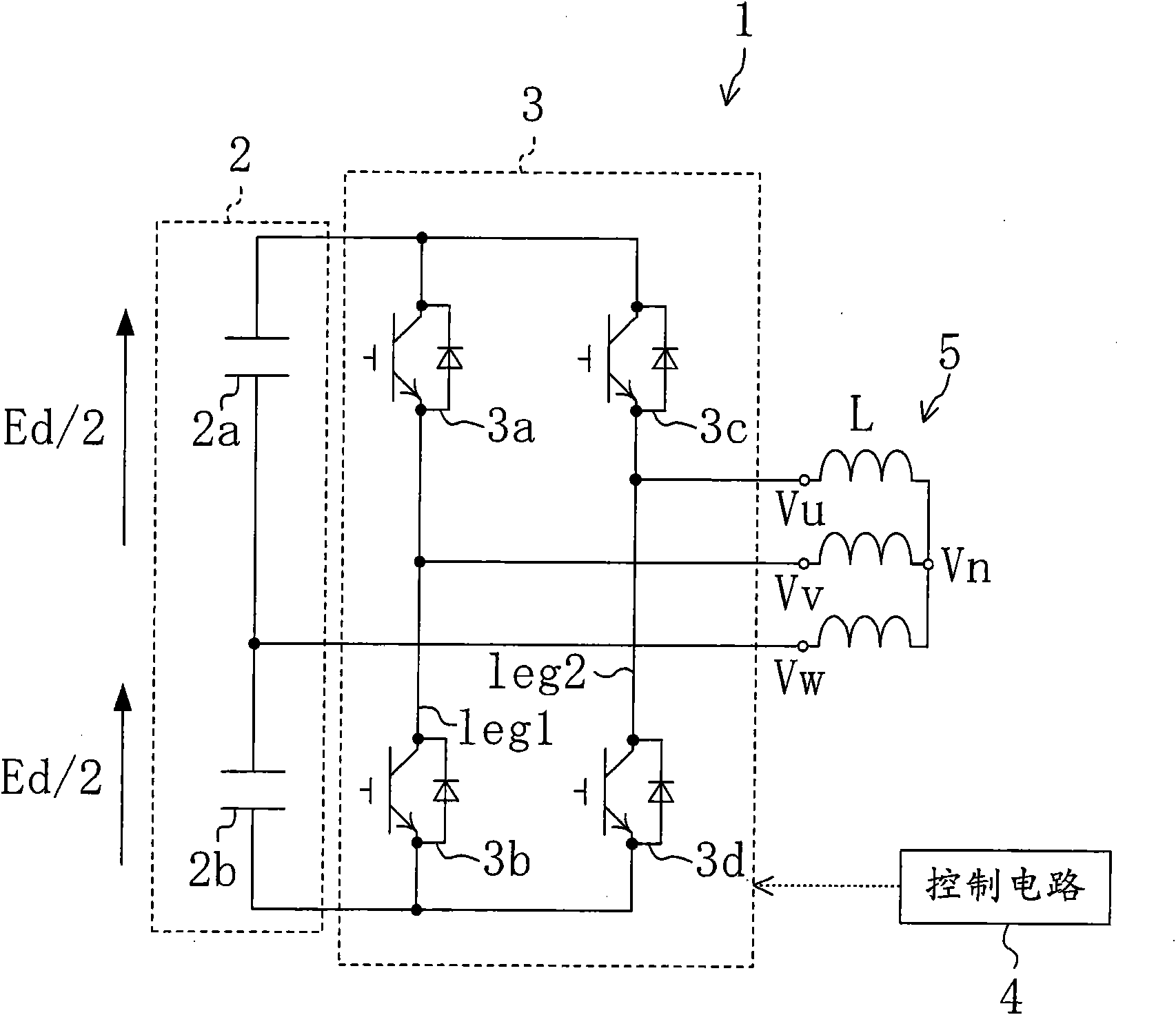
[0088] A first embodiment of the present invention will be described below. Such as figure 1 As shown, the power conversion device 1 of this embodiment includes a capacitor circuit 2 , a direct current conversion circuit 3 and a control circuit 4 (switch control mechanism). In addition, although not shown in particular, the power conversion device 1 includes a rectification circuit that rectifies an AC voltage of a commercial power supply and converts it into a DC voltage. In addition, the power conversion device 1 is used to drive, for example, an electric motor (hereinafter also referred to as a motor) of a compressor provided in a refrigerant circuit of an air conditioner.

[0089] The capacitance circuit 2 is provided so that two capacitors 2a, 2b are connected in series to a rectification circuit not shown. The capacitor circuit 2 charges and discharges the DC voltage converted by the rectification circuit.

[0090] The DC-AC conversion circuit 3 is connected in parall...

no. 2 approach

[0162] Next, a power conversion device according to a second embodiment of the present invention will be described. This power conversion device has the same structure as that of the first embodiment, but the content of control is different. Therefore, the same parts will be given the same reference numerals and only the different parts will be described below.

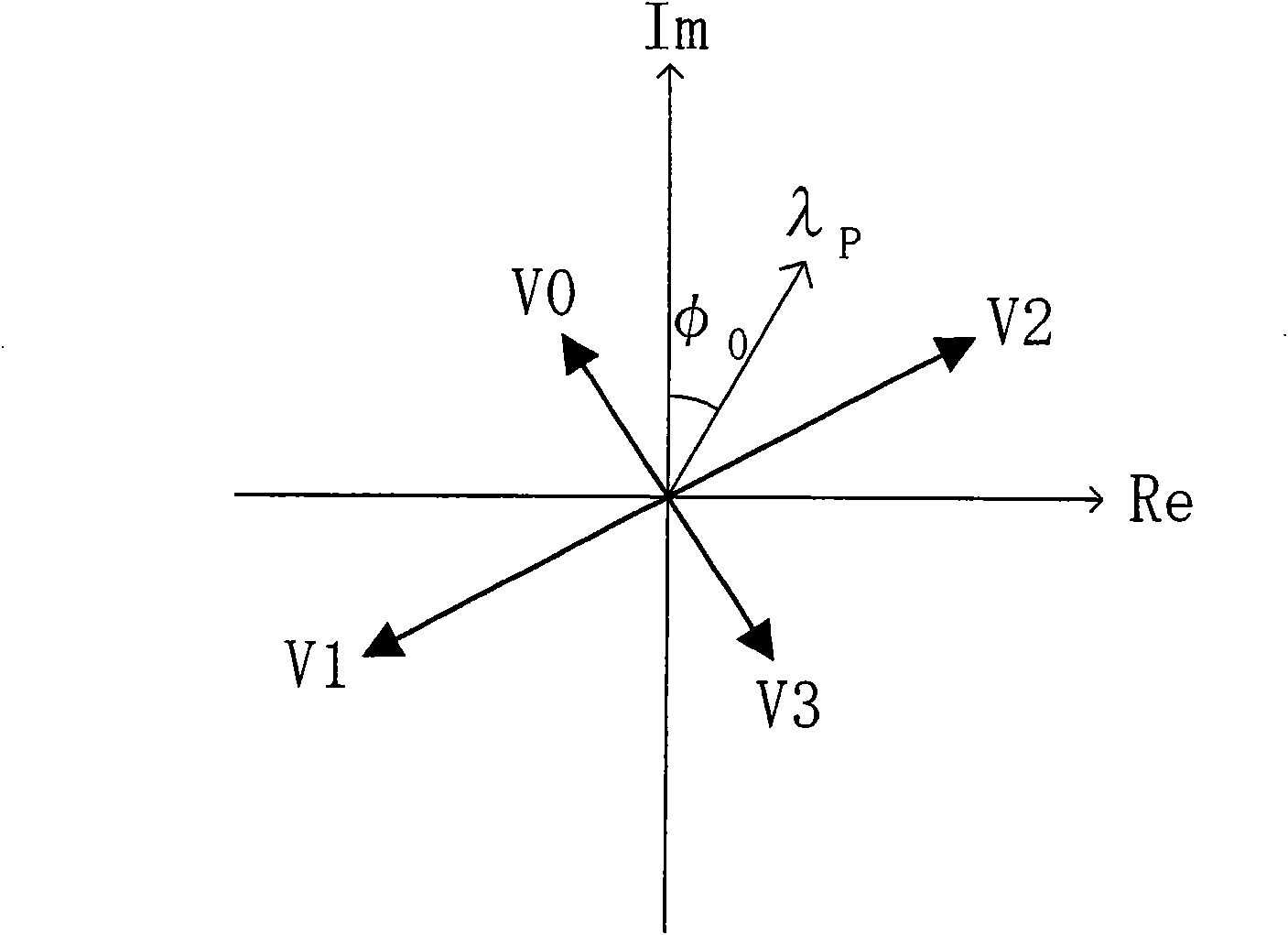
[0163] Specifically, in the second embodiment, unlike the first embodiment, three types of voltage vectors Vp obtained from the operations of the switching elements 3a, 3b, 3c, and 3d of the direct-to-alternating converter circuit 3 are used. The voltage vector depicts the flux vector λp making it a more circular locus. In addition, this embodiment is also the same as the first embodiment, such as Figure 4 As shown, the area where the magnetic flux vector λp is drawn on the complex plane is divided into four areas, and the most suitable output order and output period of the voltage vector are determined in each area...

no. 3 approach

[0198] Next, a power conversion device according to a third embodiment of the present invention will be described. This power conversion device has the same structure as the first and second embodiments, but the content of control is different. Therefore, the same parts will be given the same reference numerals and only the different parts will be described below.

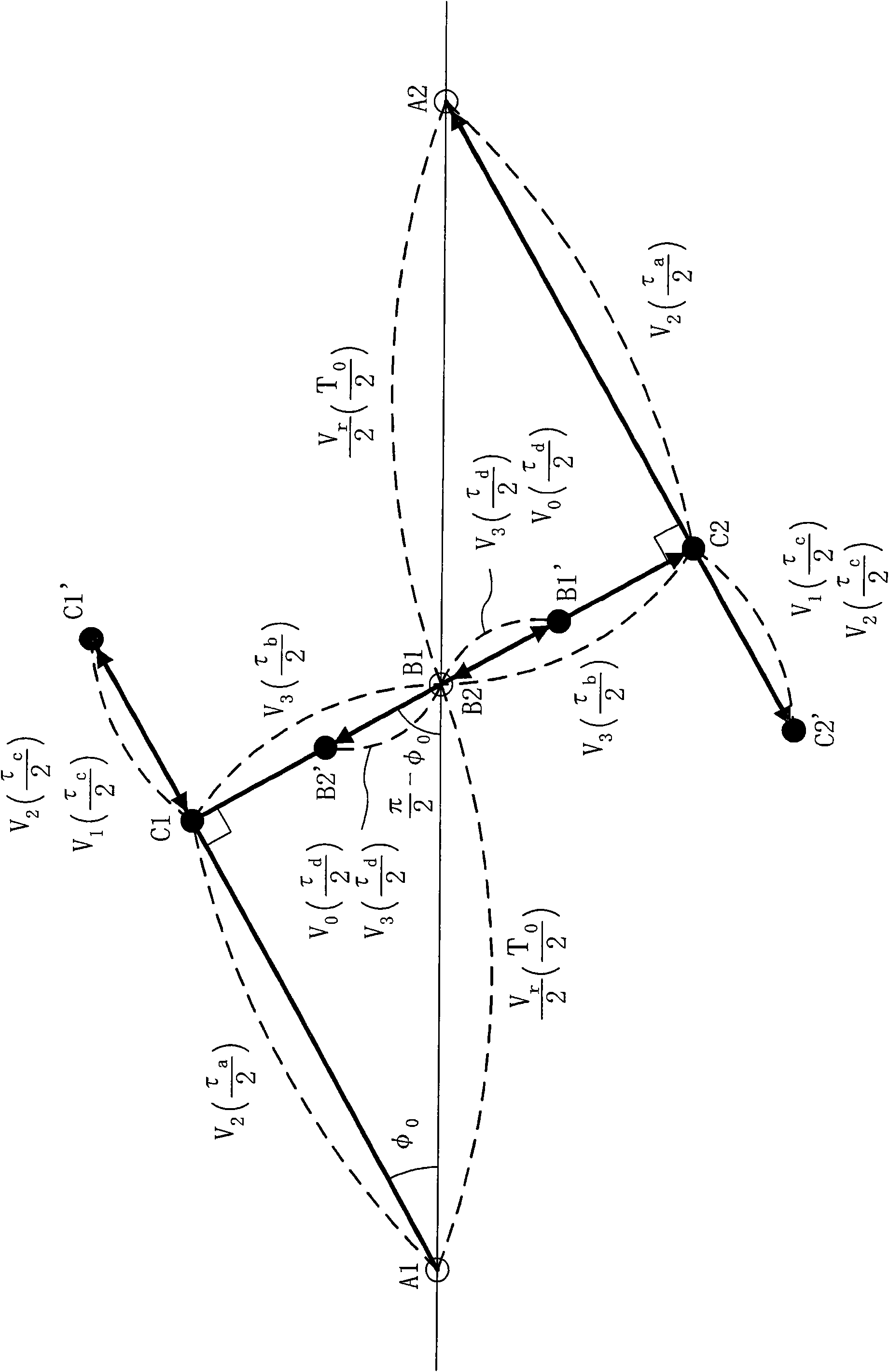
[0199] Specifically, in the third embodiment, as in the second embodiment, among the four voltage vectors Vp obtained from the operations of the switching elements 3a, 3b, 3c, and 3d of the direct-to-alternating converter circuit 3, three The voltage vector draws a locus such that the magnetic flux vector λp intersects the ideal circular locus within the half cycle period T0 / 2 of the carrier frequency. In addition, this embodiment is also the same as the first and second embodiments, such as Figure 4 As shown, the area where the magnetic flux vector λp is drawn on the complex plane is divided into four areas, and...


PUM


Abstract

The invention provides a power conversion device. In a power converter including a V connection inverter circuit, harmonic components included in output voltage are reduced to achieve a reduction in aloss of a load, such as a motor. Operation of four switching elements (3a, 3b, 3c, 3d) of a V connection inverter circuit (3) is controlled so that the locus of a flux vector p on a complex plane created by using voltage vectors Vp obtained by the operation of the switching elements (3a, 3b, 3c, 3d) approaches to a circle. Specifically, in order to create the locus of the flux vector p close toa circle by using at least three of the four voltage vectors Vp, output sequences and output periods of the voltage vectors Vp are determined.

Description

technical field [0001] The present invention relates to a power conversion device, and particularly relates to measures for reducing losses in loads such as motors due to high-frequency harmonics. Background technique [0002] Hitherto, a power conversion device that converts direct current into alternating current has been known. As such a power conversion device, for example figure 1 As shown, a power conversion device including a DC / AC converter circuit 3 including four semiconductor switches 3a to 3d and a capacitive circuit 2 in which a plurality of capacitors 2a and 2b are connected in series is known. [0003] The semiconductor switches 3a-3d of the DC-AC conversion circuit 3 are composed of transistors and diodes connected in parallel, and the figure 1 In the shown power conversion device 1 , switching legs leg1 and leg2 (switching-leg leg1 and leg2 ) formed by connecting two semiconductor switches 3 a to 3 d in series are connected in parallel to the capacitor cir...

Claims


Application Information

Patent Timeline
IPC IPC(8): H02M7/48H02M7/5387
CPCH02M1/12H02M7/53873H02M2007/53876H02M7/53876H02M7/48H02M7/5387
Inventor 芳贺仁松野澄和
Owner DAIKIN IND LTD
Why Eureka
Try Eureka