Intravascular pressure sensor

A sensor chip and pressure technology, applied in sensors, catheters, cardiac catheters, etc., can solve the problem that pressure monitors are not suitable for walking and use, and achieve the effect of minimizing trauma

Inactive Publication Date: 2010-03-31
BIOSENSE WEBSTER INC
View PDF9 Cites 14 Cited by
  • Summary
  • Abstract
  • Description
  • Claims
  • Application Information

AI Technical Summary

Problems solved by technology

However, most existing intra-arterial pressure monitors are not suitable for ambulatory use

Method used


Image

  • Intravascular pressure sensor
  • Intravascular pressure sensor
  • Intravascular pressure sensor

Examples


Embodiment Construction

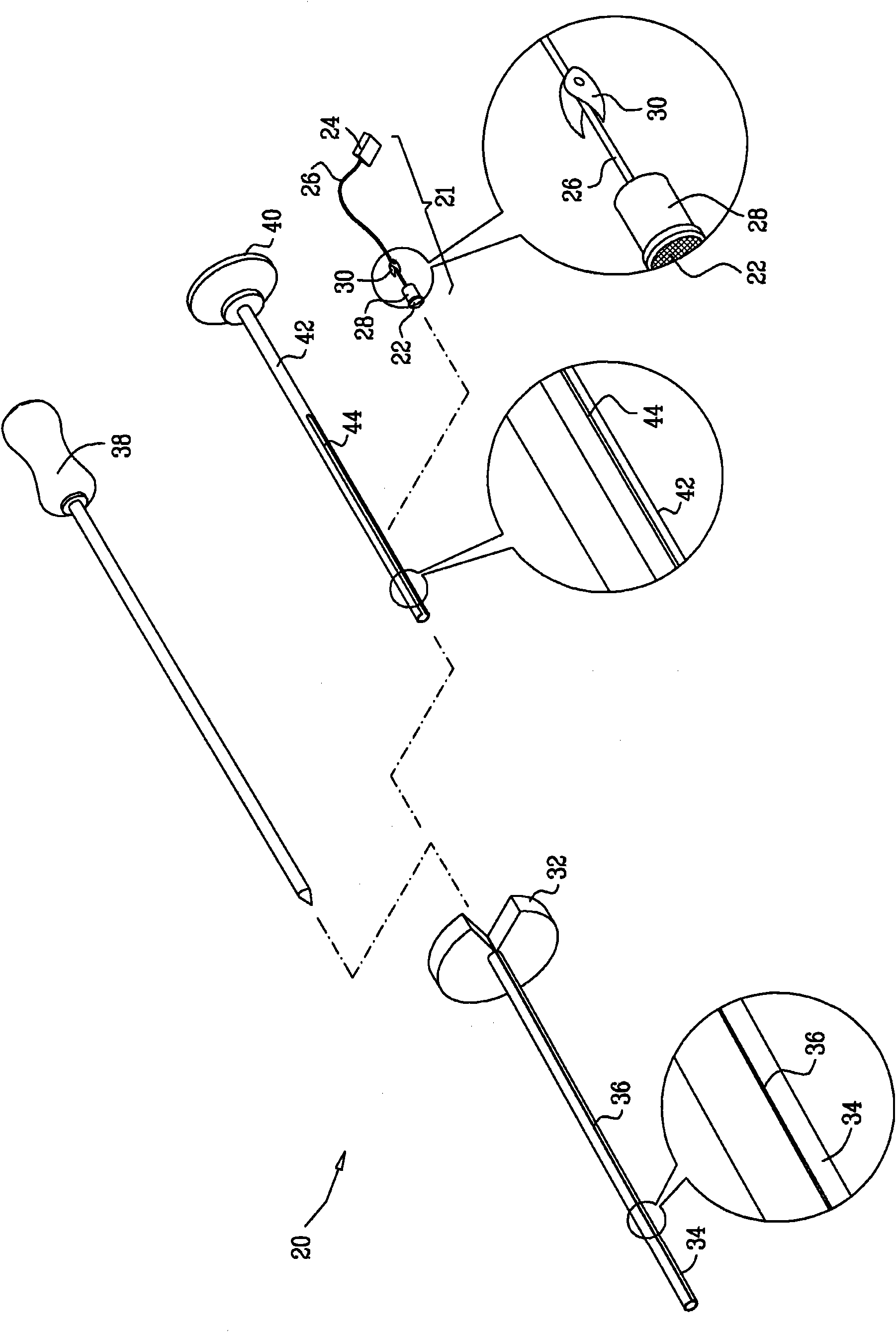
[0029] figure 1 is a schematic diagram showing a kit 20 for implanting an intravascular pressure detection device 21 according to an embodiment of the present invention.

[0030] The device 21 itself includes a sensor chip 22 for percutaneous insertion through the vessel wall, as shown in the subsequent figures. The sensor chip 22 is connected by wires 26 to an electronics package 24, which processes the electrical signals generated by the sensor chip to provide an output indicative of intravascular pressure. To facilitate insertion through the vessel wall, the lateral outer dimensions of the sensor chip are typically less than 1 mm, although larger or smaller chip sizes may be used depending on process constraints and application conditions. The electronics assembly is made of a biocompatible material suitable for implantation under the skin and can be made into a rectangular shape with sides approximately 3-4 mm long and a height approximately 0.5-0.8 mm. The electronic in...


PUM


Abstract

Pressure-sensing apparatus includes a sensor die, which is configured for percutaneous insertion through a wall of a blood vessel of a patient so as to generate an electrical signal that is responsive to a pressure in the blood vessel. A wire has a first end connected to the sensor die and a second end connected to an electronics package, which is configured for subcutaneous implantation and is connected via the wire to receive and process the electrical signal that is generated by the sensor die in order to provide an output that is indicative of the pressure.

Description

technical field [0001] The present invention relates generally to medical devices, and in particular to implantable pressure sensors. Background technique [0002] In order to properly monitor and control conditions such as hypertension, it is desirable to continuously measure the pressure within the arteries. However, most of the existing intra-arterial pressure monitors are not suitable for ambulatory use. [0003] As one possible solution, US Patent 6,053,873, the content of which is incorporated herein by reference, describes a pressure detection bracket. The flow parameter sensor is fixed on the support and measures the parameters related to the blood flow rate through the support. A transmitter transmits a signal responsive to the measured parameter to a receiver outside the body. [0004] As another example, US Patent 6,939,299, the content of which is incorporated herein by reference, describes an implantable miniature pressure sensor that integrates capacitors an...

Claims


Application Information

Patent Timeline
Patent Type & Authority Applications(China)
IPC IPC(8): A61B5/0215
CPCA61B5/6846A61B5/0215
Inventor A·戈瓦里Y·埃夫拉思Y·施瓦茨
Owner BIOSENSE WEBSTER INC
Why Eureka
Try Eureka