Reinforcement bar truss mould plate and welding process

A steel truss, welding process technology, applied in welding equipment, floors, manufacturing tools, etc., can solve the problems of waste of plates, man-hours and labor, difficult welding process, breakdown of bottom formwork, etc. The effect of mastering and improving production efficiency

Active Publication Date: 2011-05-18
TJK MACHINERY TIANJIN
View PDF0 Cites 2 Cited by
  • Summary
  • Abstract
  • Description
  • Claims
  • Application Information

AI Technical Summary

Problems solved by technology

[0005] The steel bar truss formwork of the above-mentioned prior art has the following defects: ① The angled arch bars on the bottom formwork of the prior art are usually extruded into convex edges by extrusion process on the bottom formwork, and the top surface of the angle arch bars is arc-shaped
Angle arch bars and web steel bars are welded by resistance spot welding. The bottom formwork is easily broken down during the welding process. After welding, the strength of the steel truss formwork is low, and the concrete mortar is omitted.
②During welding, in order to avoid the above-mentioned breakdown of the bottom template, the welding process needs to be strictly controlled, which is very difficult
③Squeeze the angled arch ribs at the intervals of the bottom formwork 2, wasting plates, man-hours and labor

Method used


Image

  • Reinforcement bar truss mould plate and welding process
  • Reinforcement bar truss mould plate and welding process
  • Reinforcement bar truss mould plate and welding process

Examples


Embodiment Construction

[0017] Embodiments of the present invention will be further described below in conjunction with the accompanying drawings.

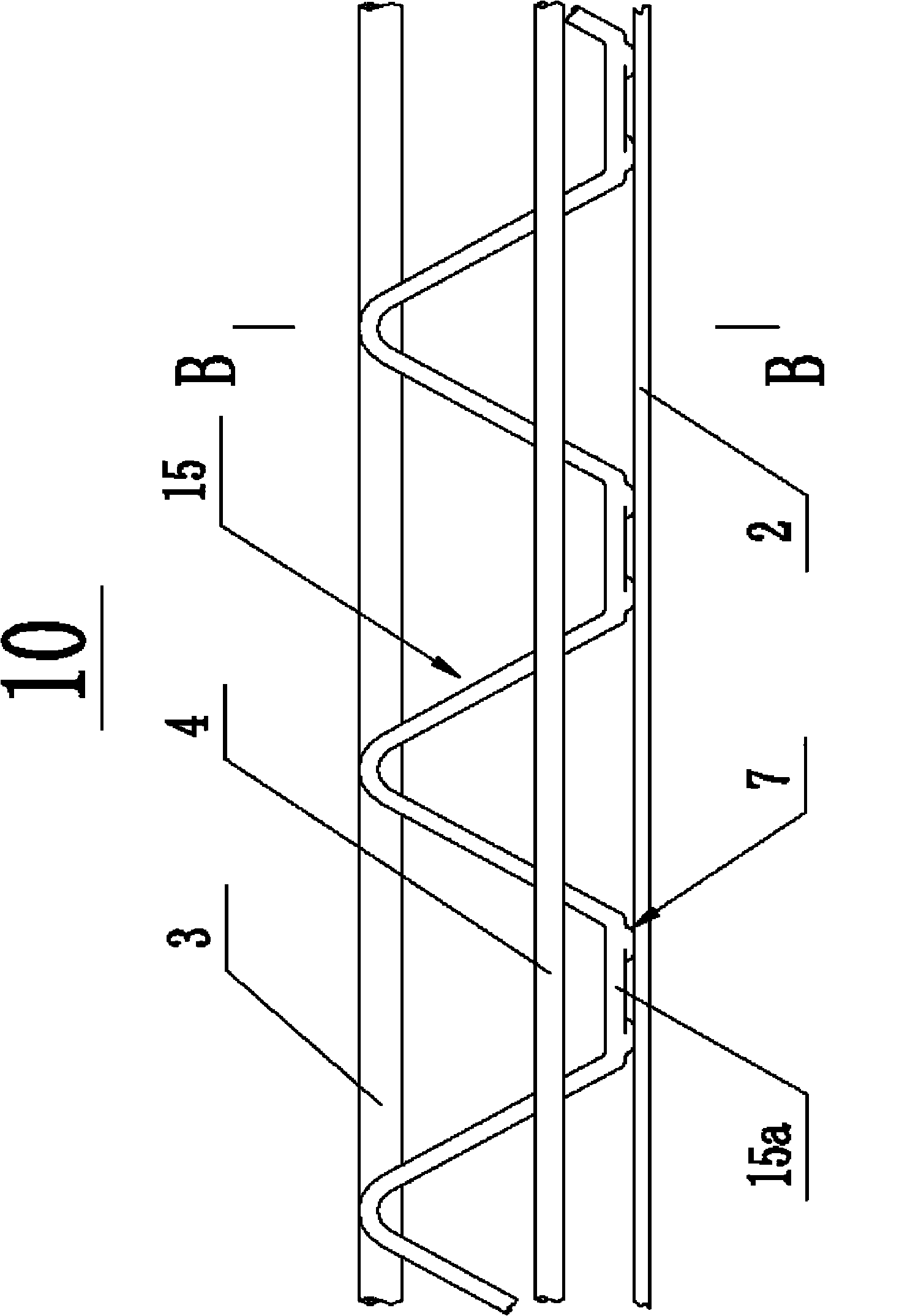
[0018] image 3 It is a structural schematic diagram of steel bar truss formwork of the present invention; Figure 4 yes image 3 The enlarged view of the B-B section.

[0019] It should be noted that the same components in the present invention and the prior art use the same serial numbers.

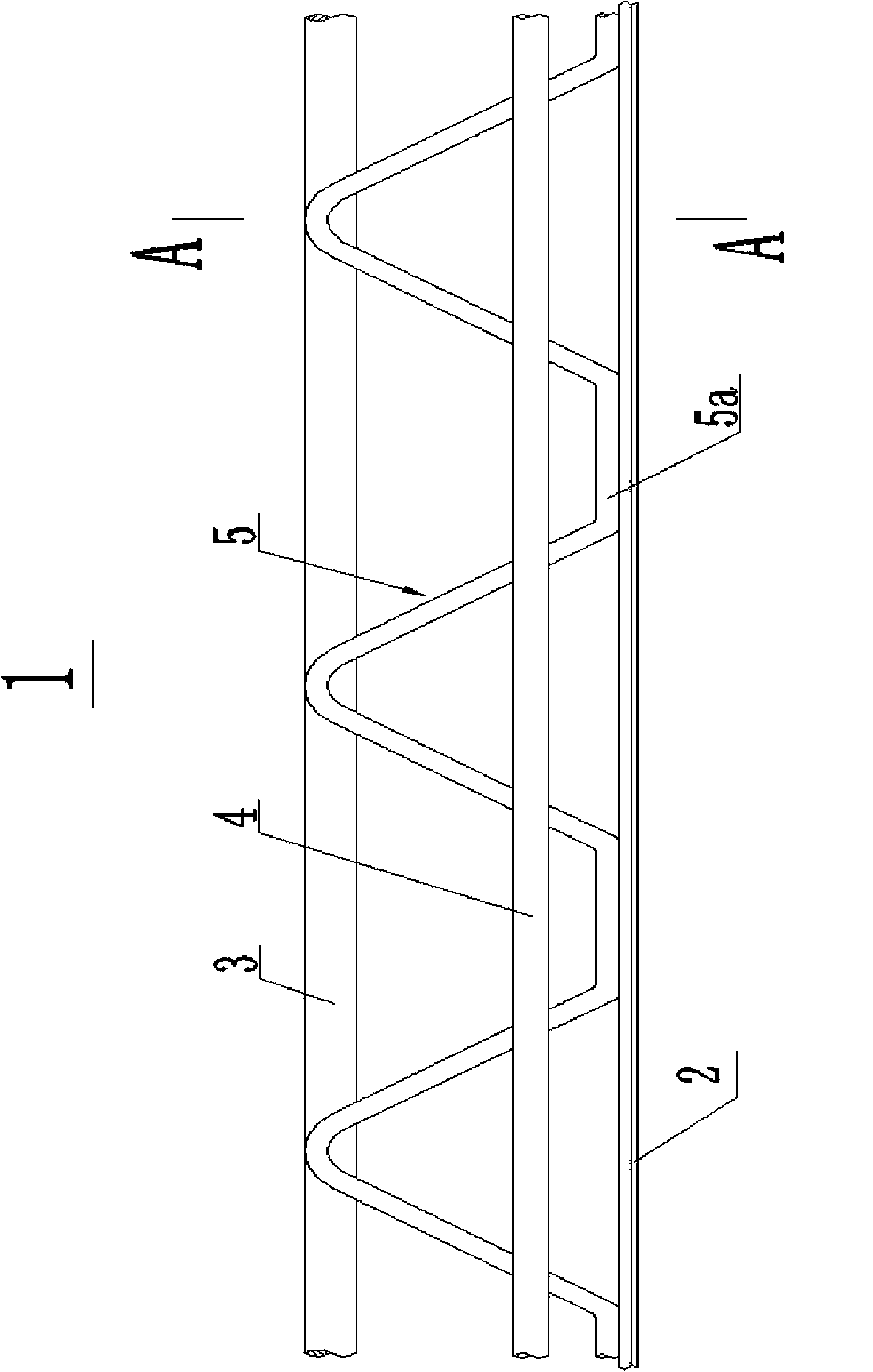
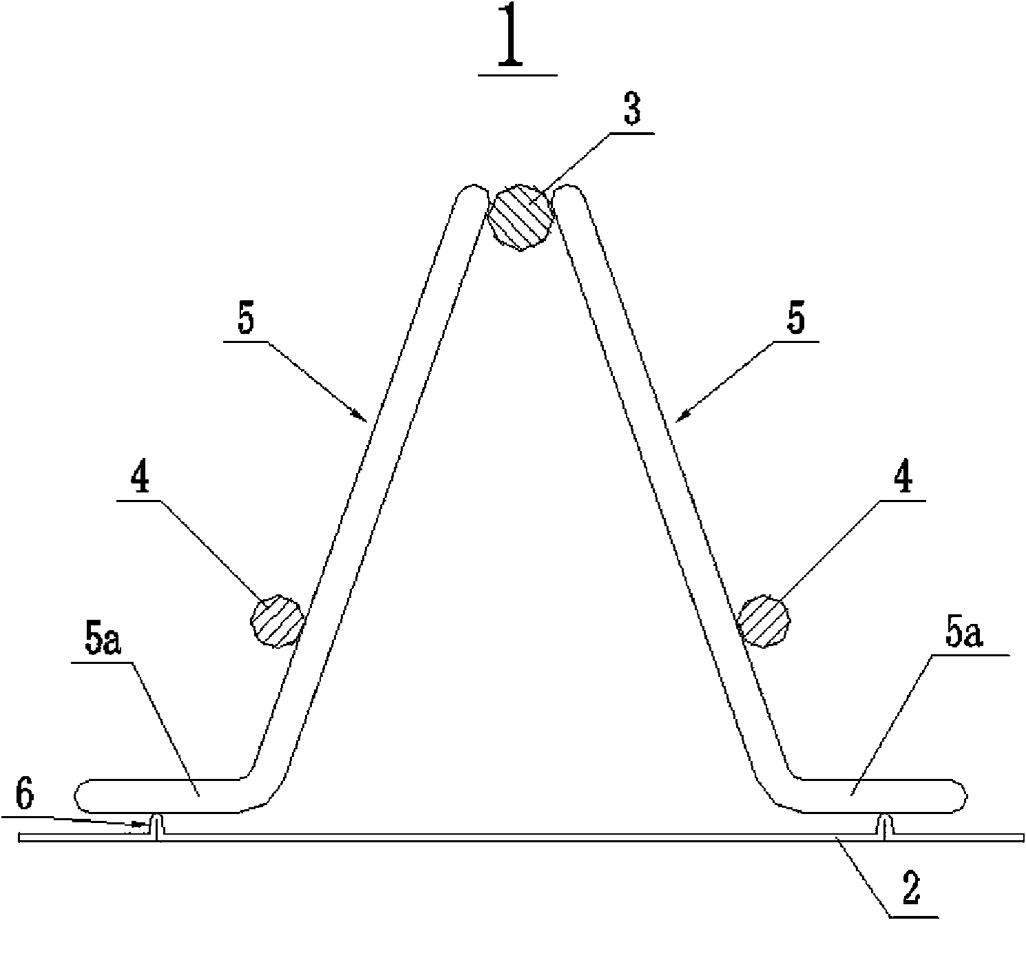
[0020] like image 3 , Figure 4 As shown, the utility model provides a steel bar truss formwork, and the steel bar truss formwork includes a steel bar truss 10 and a bottom formwork 2 .

[0021] The steel bar truss 10 includes: an upturned steel bar 3 , a downturned steel bar 4 located below the upturned steel bar 3 and a web bar 15 .

[0022] The upper ends of the web reinforcement bars 15 are welded on both sides of the upper-spin reinforcement bars 3, and the lower parts of the web reinforcement bars 15 at symmetrical positions on both sides are arranged ...


PUM


Abstract

The invention discloses a reinforcement bar truss mould plate and a welding process, wherein the reinforcement bar truss mould plate comprises a reinforcement bar truss and a bottom mould plate; the reinforcement bar truss comprises an upward spin reinforcement bar, a downward spin reinforcement bar and a web member reinforcement bar; and the bottom part of the web member reinforcement bar is parallel to the bottom mould plate and provided with a welding surface protruded toward the bottom mould plate, and the welding surface is welded on the plane of the bottom mould plate. The welding process comprises the following steps that: the bottom part of the web member reinforcement bar is bent to be parallel to the welded bottom mould plate; the bottom part of the web member reinforcement bar is downward pressed to from the welding surface; the top end parts of the two web member reinforcement bars are welded on both sides of the upward spin reinforcement bar; the downward spin reinforcement bars are welded on the symmetrical parts on the outer sides of the two web member reinforcement bars and below the upward spin reinforcement bar respectively; and the welding surface on the bottom part of the web member reinforcement bar is welded on the plane of the bottom mould plate. The reinforcement bar truss mould plate and the welding process have the advantages that: because the web member reinforcement bar and the bottom mould plate are of surface contact, the after-welding strength is improved by three times; the welding process is easily mastered, and the defects of puncturing the bottom mould plate and leaking concrete mortar are overcome; and because the bottom mould plate does not need an angle-type arc ribs, the plates, man-hours and labor are saved, and the production efficiency is improved by 40 percent.

Description

technical field [0001] The invention relates to a building component and a process, in particular to a steel bar truss formwork and a welding process. Background technique [0002] Reinforced truss formwork is a common building component, which is usually placed in concrete mortar as an embedded part to increase the strength of the concrete component. Prior art reinforced truss formwork such as figure 1 , figure 2 shown. [0003] figure 1 It is a structural schematic diagram of a steel bar truss formwork in the prior art; figure 2 yes figure 1 A-A cut-away enlarged view. [0004] The structure of the steel bar truss formwork in the prior art includes a steel bar truss 1 and a bottom formwork 2; the steel bar truss 1 includes: an upper-spin steel bar 3, an under-spin steel bar 4 and a web steel bar 5 located symmetrically on both sides below the upper-spin steel bar 3; The upper ends of the web bars 5 are welded on both sides of the upper-spin bars 3, and the lower p...

Claims


Application Information

Patent Timeline
Patent Type & Authority Patents(China)
IPC IPC(8): E04B5/40B23K11/00B23K11/34
Inventor 陈振东
Owner TJK MACHINERY TIANJIN
Why Eureka
Try Eureka