Induction heating cooker

A technology of induction heating and cooker, applied in induction heating, induction heating device, electric/magnetic/electromagnetic heating, etc., can solve the problem of ineffective heating and achieve the effect of increasing temperature

Inactive Publication Date: 2010-03-31
PANASONIC CORP
View PDF1 Cites 3 Cited by
  • Summary
  • Abstract
  • Description
  • Claims
  • Application Information

AI Technical Summary

Problems solved by technology

[0008] In this way, in the conventional induction heating cooker, the pan whose bottom is curved in a convex state and the pan with a thin bottom are overheated, and as a result, there is a problem that effective heating cannot be performed.

Method used


Image

  • Induction heating cooker
  • Induction heating cooker
  • Induction heating cooker

Examples


Embodiment approach 1

[0049] 1.1 Structure of induction heating cooker

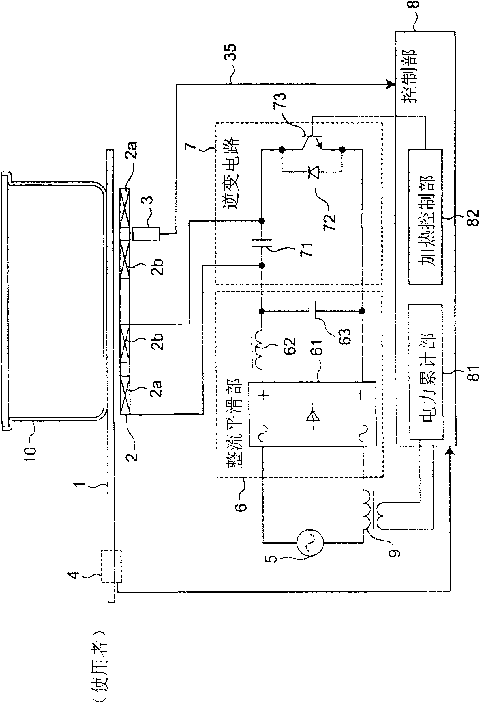
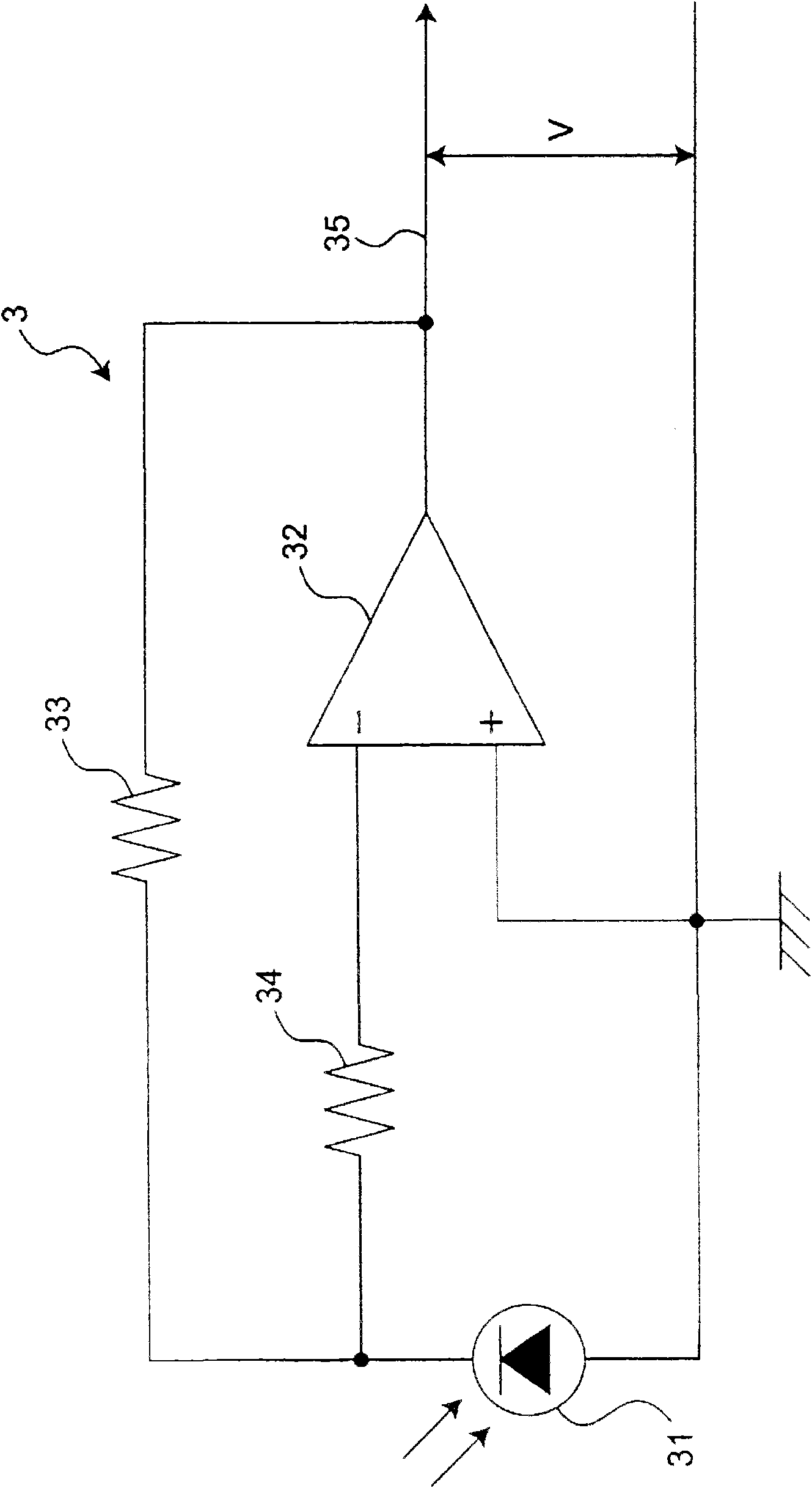
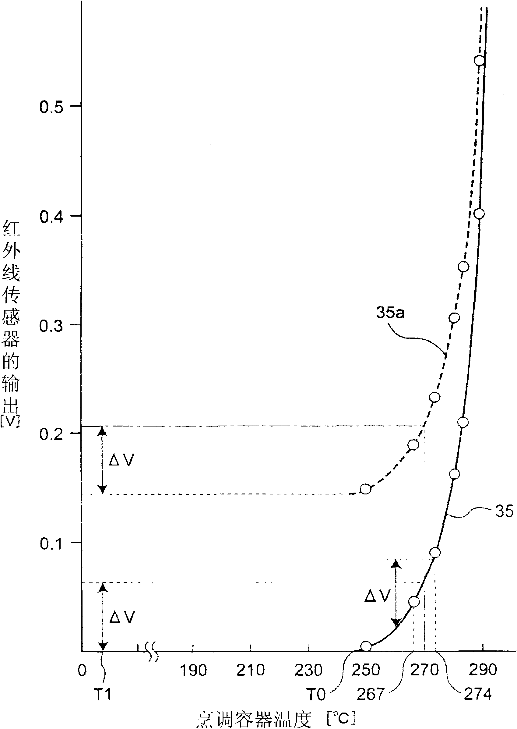
[0050] figure 1 The configuration of the induction heating cooker according to Embodiment 1 of the present invention is shown. The induction heating cooker of this embodiment has an infrared sensor 3, and heats a cooking vessel 10 such as a pan by controlling the heating electric power after the integrated value of the input electric power required for the temperature detected by the infrared sensor 3 to reach a predetermined value.

[0051] The induction heating cooker according to Embodiment 1 of the present invention includes a top plate 1 provided on the upper surface of the device, and a heating coil 2 for inductively heating a cooking container 10 on the top plate 1 by generating a high-frequency magnetic field. The top plate 1 is made of an electrical insulator such as glass, and transmits infrared rays. The heating coil 2 is arranged under the top plate 1 . The heating coil 2 is divided into two concentric circles t...

Embodiment approach 2

[0091] 2.1 Operation of induction heating cooker

[0092] In this embodiment, the control after the accumulated electric energy reaches the predetermined electric energy Wh1 or more ( Figure 4 The control after step 403) is different from Embodiment 1. In Embodiment 1, during the execution of the first heating control mode (S404) or the second heating control mode (S405), the heating control mode will not be switched to another heating control mode during the heating process, but will continue in the initially determined control mode. heating. However, in this embodiment, it is possible to switch between the first heating control mode and the second heating control mode during the heating process. The structure of the induction heating cooker of this embodiment is the same as that of Embodiment 1. As shown in FIG.

[0093] use Figure 9 ~ Figure 11 , operations different from those in Embodiment 1 will be described. Figure 9 The flow of the first heating control mode in...


PUM


Abstract

Provided is an induction heating cooker which prevents overheating of a pan whose bottom is warped to protrude and a pan having a thick bottom. The induction heating cooker is provided with a heatingcoil (2) for inductively heating a cooking container; an inverter circuit (7) for supplying the heating coil with a high frequency current; an infrared sensor (3) for detecting an infrared ray radiated from the cooking container; a power integrating section (81) for integrating a heating power outputted from the inverter circuit; and a heat control section (82) for controlling output from the inverter circuit. When the integration value obtained by the power integrating section is less than a prescribed value when an output increase quantity of the infrared sensor reaches a first prescribed value after heating is started with a first heating power, heat control mode is shifted to first heat control mode. When the integration value obtained at the power integrating section is at a prescribed value or higher, the heat control mode is shifted to second heat control mode. In the first heat control mode, the heating power is suppressed to a second heating power, which is lower than the first heating power. In the second heat control mode, heating is performed with a third heating power which is higher than the second heating power.

Description

technical field [0001] The present invention relates to an induction heating cooker for induction heating a cooking vessel. Background technique [0002] In recent years, induction heating cookers that induction-heat cooking containers such as pots and woks with heating coils have been widely used in general households and commercial kitchens. The induction heating cooker detects the temperature of the bottom surface of the cooking vessel, and controls the heating coil so that the detected temperature matches the set temperature. [0003] For example, in the induction heating cooker described in Patent Document 1, in order to detect the temperature of the bottom surface of the cooking vessel, a temperature detection unit is provided at a predetermined position on the lower surface of the top plate. This induction heating cooker first starts heating with a predetermined heating output, and temporarily stops heating when the temperature gradient of the bottom surface of the c...

Claims


Application Information

Patent Timeline
Patent Type & Authority Applications(China)
IPC IPC(8): H05B6/12
CPCH05B2213/07H05B6/062
Inventor 渡边贤治弘田泉生富永博藤涛知也矶田惠子
Owner PANASONIC CORP
Why Eureka
Try Eureka