Marsh gas pool

A biogas digester and material pond technology, applied in the field of biogas digesters, can solve problems such as reduction, and achieve the effects of reducing losses, saving water, reducing depth and volume

Inactive Publication Date: 2010-04-07
LANZHOU UNIVERSITY
View PDF1 Cites 5 Cited by
  • Summary
  • Abstract
  • Description
  • Claims
  • Application Information

AI Technical Summary

Problems solved by technology

[0008] This structure of the present invention: the water pressure room is arranged above the side of the fermentation room, which overcomes the prior art that the water pressure room is arranged on the side of the fermentation room, and the water pressure room is lower than the fermentation room, which causes the temperature of the fermentation room The lack of reduction can prevent the fermentation bacteria in the fermentation room from flowing to the water pressure room; the connecting pipe between the fermentation room and the water pressure room is located at the upper part of the fermentation room, and the mouth of the connecting pipe is 80 to 100 cm away from the bottom of the fermentation room. This structure can not only guarantee the pressure in the water pressure room, but also reduce the loss of fermentation bacteria, and save the water consumption in the water pressure room to the greatest extent, which is very beneficial for arid and water-deficient areas; on the side of the pumping tank There is a return pipe connected to the feed pipe on the wall, so that the biogas slurry brought out during the extraction of biogas residue can flow back to the fermentation room through the return pipe, so that the bacteria in the fermentation room can be kept in it to the maximum extent, and the The fermentation bacteria are evenly distributed in the fermentation room;

Method used


Image

  • Marsh gas pool
  • Marsh gas pool
  • Marsh gas pool

Examples


Embodiment Construction

[0020] The present invention is illustrated below in conjunction with the accompanying drawings.

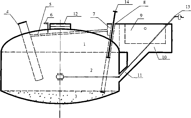
[0021] see figure 1 , above the bottom of the pool 3 of the present invention is a fermentation room 2, above the fermentation room 2 is a gas storage room 1, and the top shell above the gas storage room 1 is provided with a movable cover 12, an air guide pipe 6 and the bottom of the pool 3, The longitudinal axis of the main body of the biogas digester composed of the fermentation room and the gas storage room is a feed pipe 4 arranged obliquely. A water pressure room 10 is arranged outside the biogas digester main body. The lower bottom of the water pressure room 10 is provided with a connecting pipe 11 obliquely inserted into the fermentation room 2, and the connecting part of the connecting pipe 11 between the fermentation room and the tank bottom plane (i.e. figure 1 The part indicated by the dotted line in the middle) the distance is 80-100 cm. Depend on figure 1 It can ...


PUM


Abstract

The invention relates to a marsh gas pool, which consists of a fermentation room, a gas storage room, a pool bottom, a water pressure room, a feed pipe, a gas-guide tube and a pipeline, wherein the pool bottom and the water pressure room are positioned at the lower bottom of the fermentation room; the feed pipe and the gas-guide tube are arranged on the gas storage room; the pipeline communicates the fermentation room, the gas storage room and the water pressure room; the water pressure room is communicated with the fermentation room through a communicating pipe which is arranged in an inclination way and is 80 to 100 cm higher than the bottom of the fermentation room; a manure pumping pool is arranged besides a manure storage pool; the pool bottom of the manure pumping pool is higher than the manure storage pool; a discharge tube is arranged in the manure pumping pool; the lower end of the discharge tube extends to the bottom of the marsh gas pool; a sidewall close to the bottom of the manure pumping pool is provided with a return pipe communicated with the feed pipe; and one end of the feed pipe is positioned out of the marsh gas pool, while the other end is arranged in the fermentation room.

Description

technical field [0001] The invention relates to a biogas digester, which consists of a fermentation room, a gas storage room, a pool bottom located at the bottom of the fermentation room, a water pressure room, a feeding pipe arranged on the gas storage room, an air guide pipe, and a connecting fermentation room. Room, gas storage room, and hydraulic room are composed of pipelines. Background technique [0002] The use of plant residues and animal feces to ferment biogas has been widely promoted in rural areas of our country, thus forming a variety of biogas digesters. [0003] In the fully automatic biogas digester disclosed in Chinese invention patent application 20051009975.X, a feed pipe is set on the fermentation room, the fermentation room is connected to the discharge room through the discharge port, an oxygen delivery pipe is provided on the top of the fermentation room, and an overflow is provided on the upper part of the settling room There is a slag discharge val...

Claims


Application Information

Patent Timeline
Patent Type & Authority Applications(China)
IPC IPC(8): C12M1/107C02F11/04
CPCY02E50/343C12M21/04C12M29/20Y02E50/30
Inventor 丁文广张克勤孟作宏吴洋汪霞高雅玉
Owner LANZHOU UNIVERSITY
Why Eureka
Try Eureka