

Steel structured wide-bay energy-saving residential building with gypsum walls and on-site layering and sectioning manufacturing method
A technology of residential buildings and large bays, which is applied in the direction of residential buildings, buildings, building components, etc., to achieve the effects of saving clay resources, saving construction costs, and solving the problems of anti-corrosion and fire prevention
- Summary
- Abstract
- Description
- Claims
- Application Information
AI Technical Summary
Problems solved by technology
Method used
Image

Examples
Embodiment Construction
[0022] The present invention will be further described in detail below in conjunction with the accompanying drawings and embodiments, but it is not used as a basis for any limitation of the present invention.
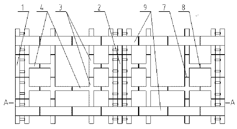
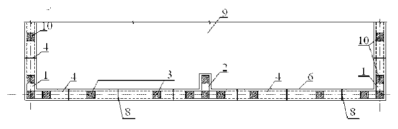
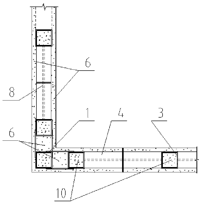
[0023] Embodiment of the present invention: When making a large-bay residential building with a room width of ≤12 meters, a depth of ≤9 meters, and a number of floors n≤15, the energy-saving house with a steel structure gypsum wall of the present invention is adopted. The building is manufactured in layers and sections on site. The steel grid frame is used as the skeleton of the exterior wall or load-bearing wall of the residential building. The steel grid frame is made of pre-welded and formed steel components in the factory, which are spliced and connected into a network on site. grid-shaped steel grid frame, and the on-site connection between the steel components and steel components is carried out by high-strength bolts. When splicing the steel grid frame, each floor...
PUM
 Abstract
Description
Claims
Application Information