Multi-functional tripod with continuous angle change

An angle-changing, multi-functional technology, applied in the field of equipment devices, can solve problems such as increased probability of failure, inability to adapt to complex environments, and increased cost of tripods, and achieves the effects of convenient operation, light weight, and simple and compact structure.

Inactive Publication Date: 2010-04-07
SUZHOU SYNTA OPTICAL TECH
View PDF2 Cites 12 Cited by
  • Summary
  • Abstract
  • Description
  • Claims
  • Application Information

AI Technical Summary

Problems solved by technology

However, if it is necessary to continuously fine-tune the span of the leg tube in an environment with changing terrain, it is more difficult for this tripod
[0004] Equally, be that CN1936690, disclosure date are that the camera tripod that the invention patent on March 28, 2007 proposes as Chinese publication number also has similar defects, and it is provided with between the support leg support pipe seat and the tripod main body to adjust the opening angle of

Method used


Image

  • Multi-functional tripod with continuous angle change
  • Multi-functional tripod with continuous angle change
  • Multi-functional tripod with continuous angle change

Examples


Embodiment 1

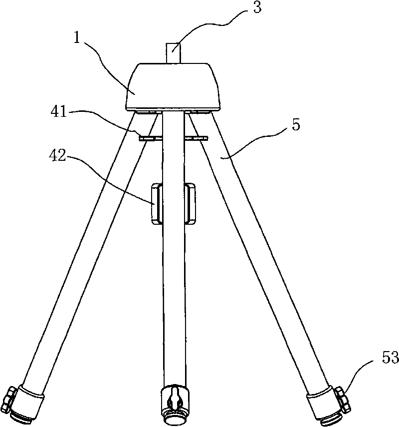
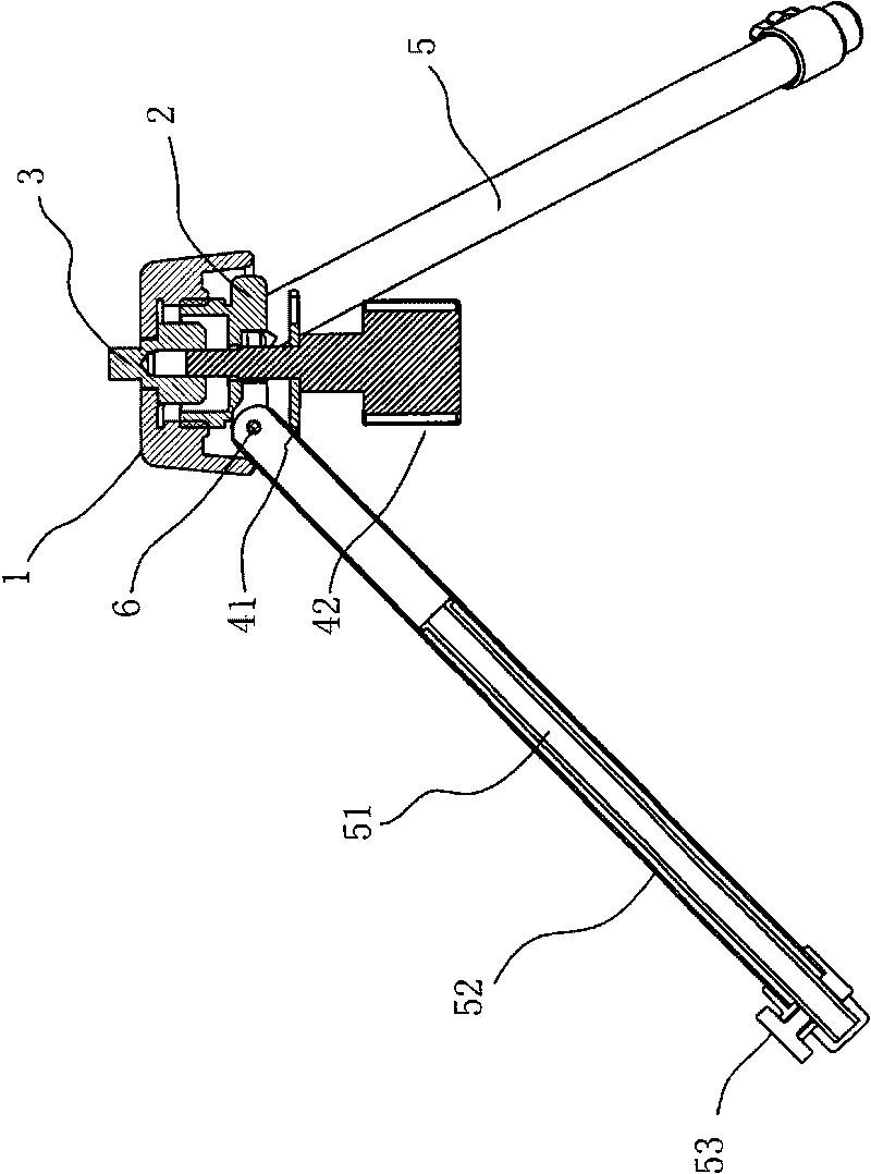
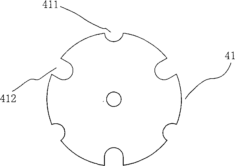
[0041] Example 1 as Figure 1~3 As shown, the multifunctional tripod that can continuously change the angle includes a connecting head 3 , a connecting base 2 , three legs 5 , an adjusting cover 1 , a supporting plate 41 and a bolt 42 . The upper end of the connector 3 is connected with a cloud platform. The connecting seat 2 is arranged in the adjusting cover 1, and the inner wall of the adjusting cover is combined with the upper part of the connecting seat through a thread structure with a certain length. The upper part of the connecting seat is a cylindrical structure, the upper end of which is open, and a through hole is arranged at the center of the lower end. The upper end of the leg is hinged to the lower part of the connecting seat through a rivet 6 . The support plate 41 is provided between the respective legs 5 . The connecting head 3, the adjusting cover 1, the connecting seat 2 and the support plate 41 are arranged coaxially in the vertical direction. A threade...

Embodiment 2

[0054] Example 2 as Figure 7-10 As shown, the variable-span multifunctional tripod includes a connection base 2', three legs 5, an adjustment cover 1', a bowl-shaped support 41' and a bolt 42'. A pan-tilt connector 3' is integrally arranged on the upper end of the adjustment cover. The connecting seat is arranged under the adjusting cover, and the connecting seat 2' is combined with the inner wall of the adjusting cover 1' by screwing. The upper end of each leg 5 is hinged to the lower peripheral edge of the connecting seat 2' through a rivet, and the support member 41' is arranged between each leg 5. A threaded blind hole is vertically arranged at the center of the lower end surface of the connecting seat 2', and the upper end of the bolt vertically passes through a through hole provided at the center of the support plate to combine with the threaded blind hole, and its lower end is a handle. The bowl at the upper end of the support 41' extends radially to form a ring stru...


PUM


Abstract

The invention relates to a multi-functional tripod with continuous angle change, which comprises a connection seat, at least three support legs, a regulation cover and a support component, wherein the regulation cover and the support component are respectively arranged above and below the connection seat, each support leg is arranged at the periphery of the support component, the upper end of each support leg is movably connected with the connection seat, a distance among the regulation cover, the connection seat and the support component can be regulated in an upright direction and can be relatively fixed at any one position of the regulation cover, the connection seat and the support component, and the lower end of the regulation cover and the support component clamp and fix the support legs, so that an included angle between the support legs and a horizontal plane can be regulated at will within a range of 0-90 degrees along with the change of the relative positions of the regulation cover, the connection seat and the support component. The invention has simple and compact structure, small volume, light weight, low cost and convenient operation, and the span of the support legs can be regulated at will with a range of 0-180 degrees, so that the invention can be quickly and stably erected in various complicated environments. The invention can be widely applied to the fields of observation, photography, illumination and the like.

Description

Technical field: [0001] The invention relates to a device for supporting equipment such as a telescope, a camera, a video camera or a detector, and in particular to a multifunctional tripod whose angle can be continuously changed. Background technique [0002] A tripod is a device that uses the principle of three-point fixed surface, and it is mainly used to support equipment such as measuring instruments, cameras, lighting equipment and experimental equipment. Commonly used tripods generally achieve the effect of adjusting the height of the support by means of telescopic legs, so that the equipment supported by it can run stably at a certain height. With the continuous expansion of the application range of tripods, people also put forward increasingly strict requirements for their functions. For example, for observation equipment such as astronomical telescopes, if the equipment shakes or vibrates slightly during the observation process, it will easily lead to observation ...

Claims


Application Information

Patent Timeline
IPC IPC(8): F16M11/32
CPCF16M11/32F16M11/36F16M11/16F16M11/2057
Inventor 沈达忠
Owner SUZHOU SYNTA OPTICAL TECH
Why Eureka
Try Eureka