
Control method of wind collecting-type vertical-shaft fan and wind generating set thereof

A technology of wind power generators and control methods, which is applied to the combination of wind power motors, wind power generators at right angles to the wind direction, control of wind power power generators, etc., can solve problems such as reducing control reliability, increasing control costs, and structural fatigue, and achieve improved Effects of wind speed and fan efficiency, reduced bending moment strength requirements, and reduced material costs

Inactive Publication Date: 2010-04-14
李锋
View PDF0 Cites 11 Cited by
  • Summary
  • Abstract
  • Description
  • Claims
  • Application Information

AI Technical Summary

Problems solved by technology

[0002] In order to achieve high wind energy efficiency and power control during the operation of the wind turbine, the current control methods basically use pitch technology and yaw technology. This method is effective for the control of horizontal axis models, but it is used for vertical axis models. , Especially for large-scale ones, there are not small problems in these technologies: first, the blades of the vertical axis fan run at a linear speed on the circumference of the wind rotor, and the precessive torque when adjusting the pitch angle to rotate the blades will easily cause the blades to vibrate and cause structural fatigue. The safety and service life of the fan are reduced; the second is that the distance between the blades of the vertical shaft fan is relatively large, and the drive mechanism of the pitch angle, especially the mechanism of the hydraulic or pneumatic components at the joint of motion and static is complicated, which increases the control cost and reduces the Control reliability; the third is that the vertical axis fan has no yaw phenomenon and no yaw technology at all

Method used


Image

  • Control method of wind collecting-type vertical-shaft fan and wind generating set thereof
  • Control method of wind collecting-type vertical-shaft fan and wind generating set thereof
  • Control method of wind collecting-type vertical-shaft fan and wind generating set thereof

Examples


Embodiment Construction

[0054] The present invention will be further described below in conjunction with the accompanying drawings and embodiments.

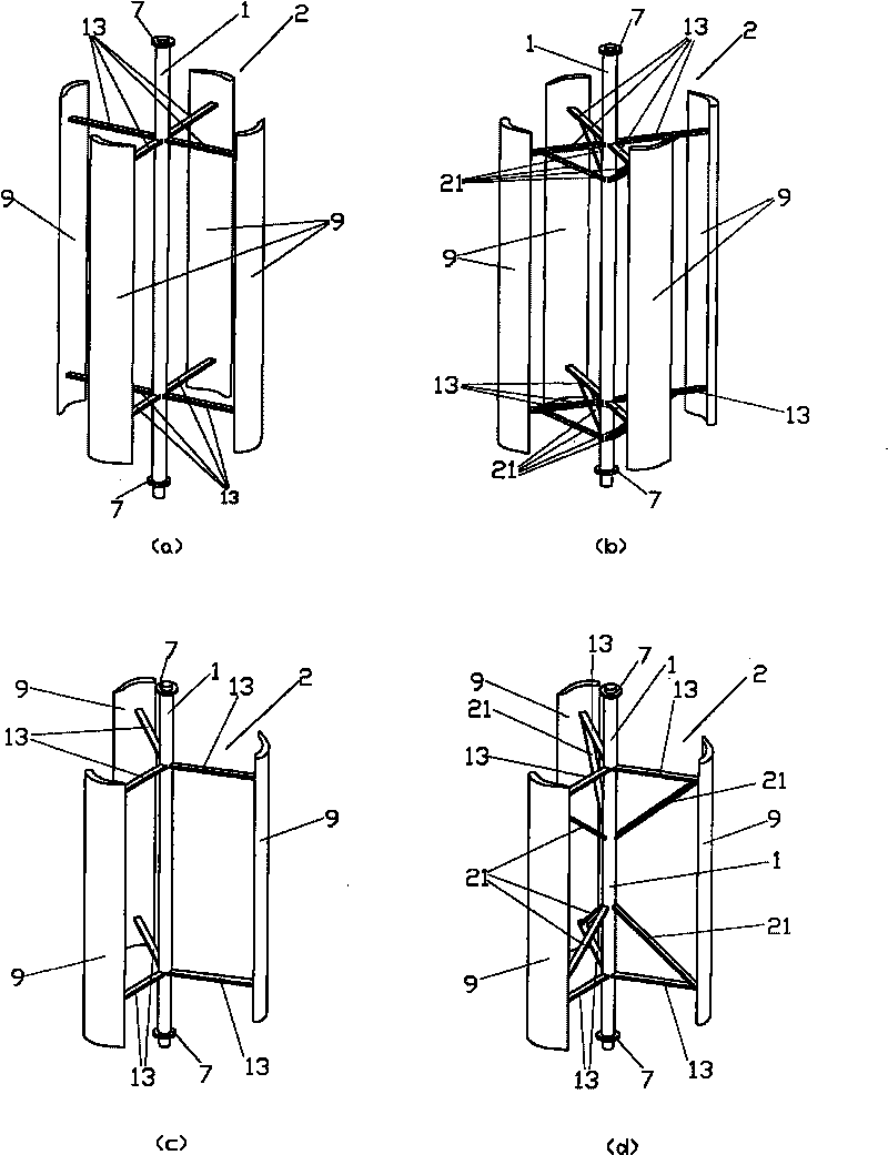
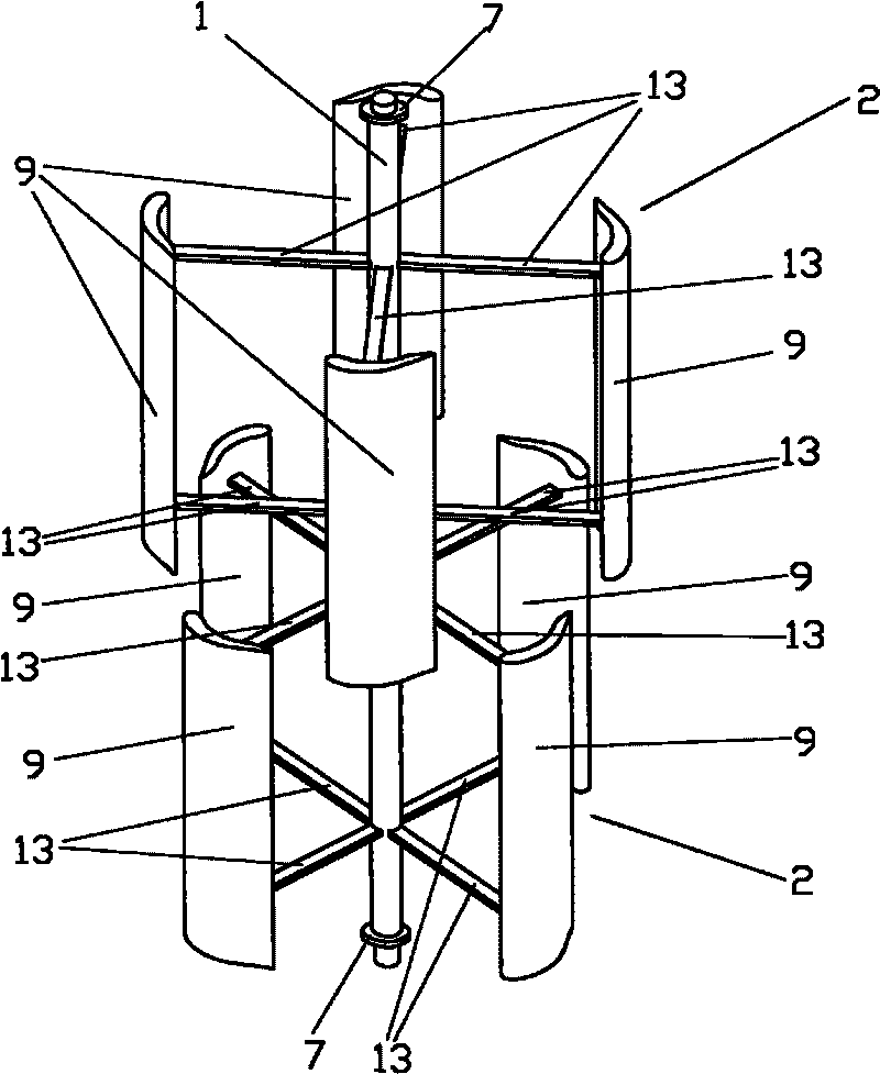
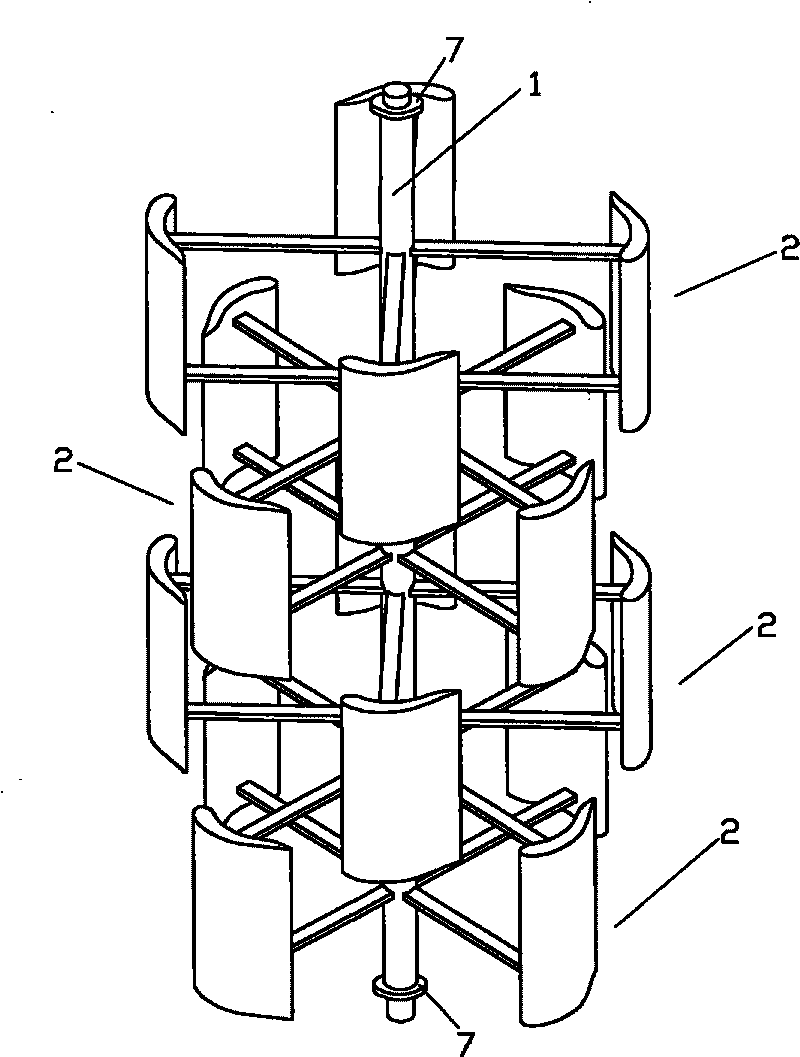
[0055] Figure 13 (b) is a schematic structural view of Embodiment 1 of the present invention, which consists of figure 1 Main shaft 1 shown in (a), a four-blade wind wheel 2 and bearing 7, Figure 8 The pentagonal tower shown in (a) 3, Figure 12 (a) and the wind guide shown in (c) 8, Figure 18 and Figure 12 (c) shown driver 18 and transmission 20, Figure 13 The base 10 shown in (a) consists of a gearbox 11 and a generator 12; a four-blade wind wheel 2 is fixedly connected to the main shaft 1, the main shaft 1 is installed at the center of the tower 3 through the bearing 7, and the wind wheel 2 is installed Inside the tower 3, the tower 3 is fixed on the base 10, the gearbox 11 and the generator 12 are installed in the base 10 below the tower 3, the low-speed shaft of the gearbox 11 is connected to the bottom end of the main shaft 1, The high-...


PUM


Abstract

The invention discloses a control method of a wind collecting-type vertical-shaft fan and a wind generating set thereof. The method is characterized in that the inflow wind speed, the relative wind speed, the attack angle of blades and the driving force of wind wheels are controlled by adjusting the position angle of a wind collecting system of the wind collecting-type vertical-shaft fan, thus being capable of controlling wind energy efficiency and fan power; a wind collecting-type vertical-shaft wind-driven generator mainly consists of a main shaft, a wind wheel, a tower post, bearings, a pedestal, a gear box, a generator and the wind collecting system, wherein the wind collecting system mainly consists of a wind guiding wing, a wind collecting wing and a driving and controlling component; and the purpose of controlling the wind energy efficiency and the fan power is achieved by adjusting and controlling azimuth angels of the wind guiding wing and the wind collecting wing.

Description

technical field [0001] The invention belongs to the design and manufacture technology of a wind power generating set, in particular to a control method of a wind-collecting vertical shaft (also called a vertical axis) fan and the wind power generating set. Background technique [0002] In order to achieve high wind energy efficiency and power control during the operation of the wind turbine, the current control methods basically use pitch technology and yaw technology. This method is effective for the control of horizontal axis models, but it is used for vertical axis models. , Especially for large-scale ones, there are not small problems in these technologies: first, the blades of the vertical axis fan run at a linear speed on the circumference of the wind rotor, and the precessive torque when adjusting the pitch angle to rotate the blades will easily cause the blades to vibrate and cause structural fatigue. The safety and service life of the fan are reduced; the second is ...

Claims


Application Information

Patent Timeline
IPC IPC(8): F03D7/06F03D9/00F03D3/00F03D3/06F03D9/25
CPCY02E10/72Y02E10/74
Inventor 李锋
Owner 李锋
Learn More