Cutting blade for processing soft metal materials

A technology of metal materials and cutting inserts, applied in metal processing equipment, tools for lathes, turning equipment, etc., can solve the problem of uncut chip curling and good control of flow direction, too smooth connection between tool tip and rake face, The smoothness of the product does not meet the requirements and other problems, so as to achieve the effect of cutting lightly, improving the processing quality and reducing contact

Active Publication Date: 2010-04-21
ZHUZHOU CEMENTED CARBIDE CUTTING TOOLS CO LTD
View PDF1 Cites 13 Cited by
  • Summary
  • Abstract
  • Description
  • Claims
  • Application Information

AI Technical Summary

Problems solved by technology

For soft metal materials, an initial bend will be obtained during the machining process, and the chips may move and extend along the rake face on the chip removal platform in an integral form, and naturally curl and fall, causing the cutting temperature to rise during the cutting process. High, for the processing of soft metal materials, the contact between chips and the rake face and the increase of cutting temperature will make the chips stick to the rake face of the insert, resulting in changes in the actual machining rake angle of the insert
During this process, the curling of the chips, the flow direction of the chips and the contact between the chips and the rake face cannot be artificially controlled or

Method used


Image

  • Cutting blade for processing soft metal materials
  • Cutting blade for processing soft metal materials
  • Cutting blade for processing soft metal materials

Examples


Embodiment Construction

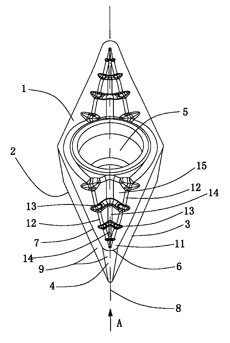
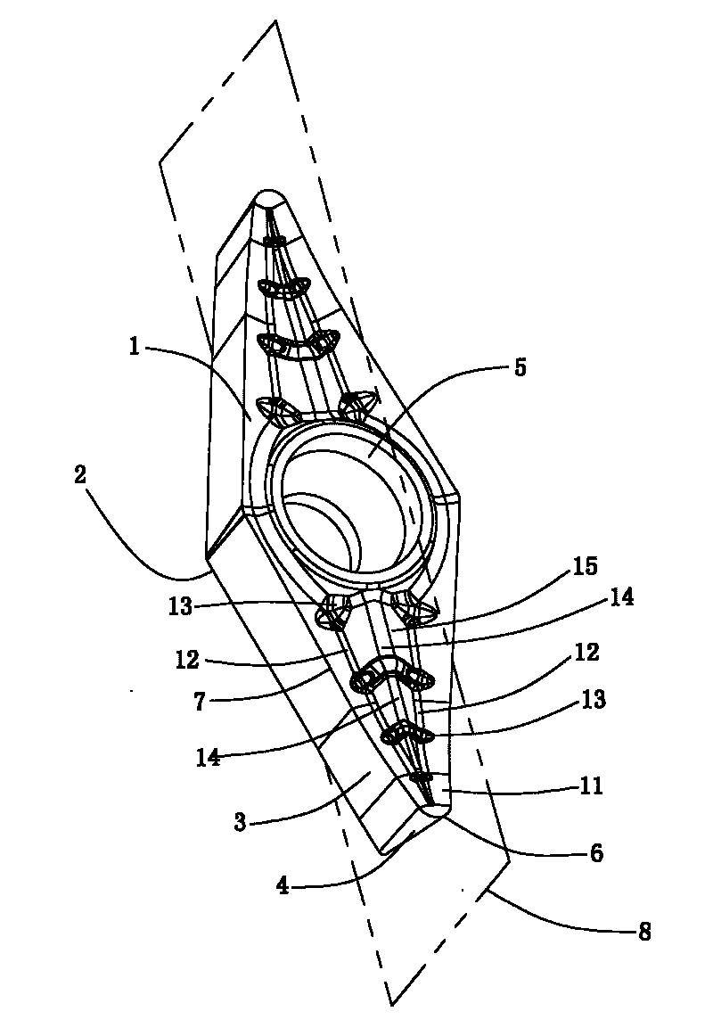
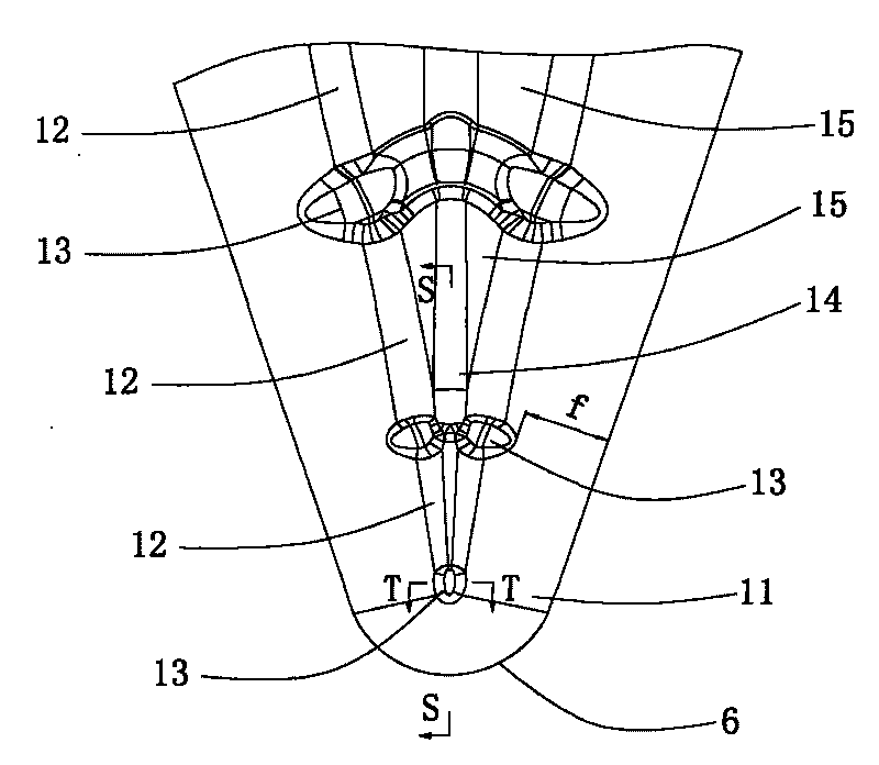
[0029] Such as Figure 1 to Figure 6 As shown, a cutting insert for processing soft metal materials of the present invention has a basic shape similar to a rhombus, including an insert surrounded by an upper surface 1, a lower surface 2, a pair of side surfaces 3 and a conical surface 4 The body, the center of the blade body is provided with a blade positioning hole 5, the upper surface 1 and the lower surface 2 are connected by the pair of side surfaces 3 and the conical surface 4, the conical surface 4 intersects with the upper surface 1 to form a main cutting edge 6, and the two sides 3 and the upper surface The surface 1 intersects to form two side cutting edges 7 respectively connected to the two sides of the main cutting edge 6. The main cutting edge 6 and the two side cutting edges 7 are symmetrically arranged on both sides of the longitudinal vertical section 8 of the insert. The main cutting edge 6 and the side The cutting edge 7 is connected into a space spiral shape...


PUM


Abstract

The invention discloses a cutting blade for processing soft metal materials. The cutting blade comprises an upper surface, a lower surface, a pair of side faces and a blade body which is enclosed by a conical surface for connecting the pair of side faces. The blade body is provided with a blade positioning hole, and the upper surface and the lower surface are connected through the pair of side faces and the conical surface. The conical surface and the upper surface are intersected into a main cutting edge, and the two side faces and the upper surface are intersected into two side cutting edges which are respectively connected on two sides of the main cutting edge. The upper surface is sunk toward the lower surface to form a rake face, a concave curved surface for guiding chips and more than two chip breakers in a shape of an elliptical lug boss. The chip breakers are uniformly distributed in a height increasing stepped shape from a position close to the main cutting edge to the blade positioning hole. The concave curved surface is connected between two adjacent chip breakers; and the rake face extends toward the middle of the upper surface from the main cutting edge and two side cutting edges, and is connected with the concave curved surface. The cutting blade has the advantages of controlling shapes and flow directions of the chips, decreasing the contact between the chips and the upper surface of the blade, and reducing the cutting temperature.

Description

technical field [0001] The invention relates to a turning insert for metal cutting, in particular to a cutting insert for processing soft metal materials. Background technique [0002] The turning insert structure for processing soft metal materials generally has a sharp rake angle and a chip removal space with a large opening. In this type of structure, there is a plane or an arc between the rake face and the chip removal platform connected face to face. In this way, during the cutting process, the chips are removed by the cutting edge at the tip of the insert, and then slide along the rake face to the plane or arc surface connected with the chip removal platform, and then are discharged through the chip removal platform. For soft metal materials, an initial bend will be obtained during the machining process, and the chips may move and extend along the rake face on the chip removal platform in an integral form, and naturally curl and fall, causing the cutting temperature t...

Claims


Application Information

Patent Timeline
IPC IPC(8): B23B27/22
Inventor 刘敏李树强吕长江王社权李屏
Owner ZHUZHOU CEMENTED CARBIDE CUTTING TOOLS CO LTD
Why Eureka
Try Eureka