

Abrasive wheel saw clamping mechanism
A technology of clamping mechanism and grinding wheel saw, which is applied in the direction of grinding machines, metal processing equipment, grinding/polishing equipment, etc., can solve the problem of large space occupation, and achieve the effect of saving space and good sawing effect
Inactive Publication Date: 2011-01-05
JIANGYIN DONGCHEN MACHINERY MFG
View PDF0 Cites 0 Cited by
- Summary
- Abstract
- Description
- Claims
- Application Information
AI Technical Summary
Problems solved by technology
Before the present invention was made, the conventional grinding wheel saw clamping mechanism was not made on the machine body. When the bar was sawed, the section was not perpendicular to the bar. When the horizontal clamping device of the clamping device was moved out of the roller table, it took up a lot of space.
Method used
View moreImage
Smart ImageViewing Examples

Examples
Embodiment Construction
Login to View More PUM
 Abstract
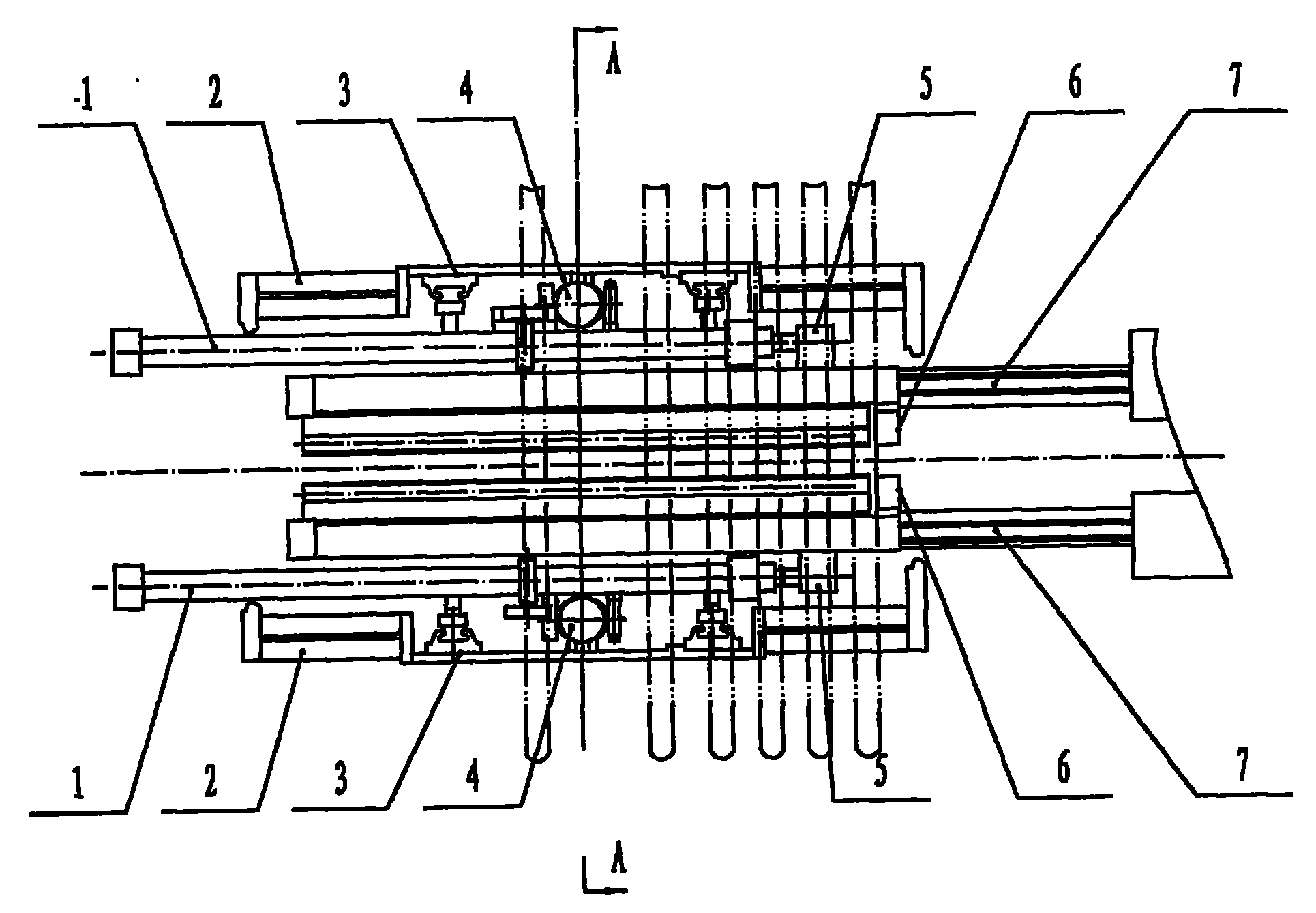
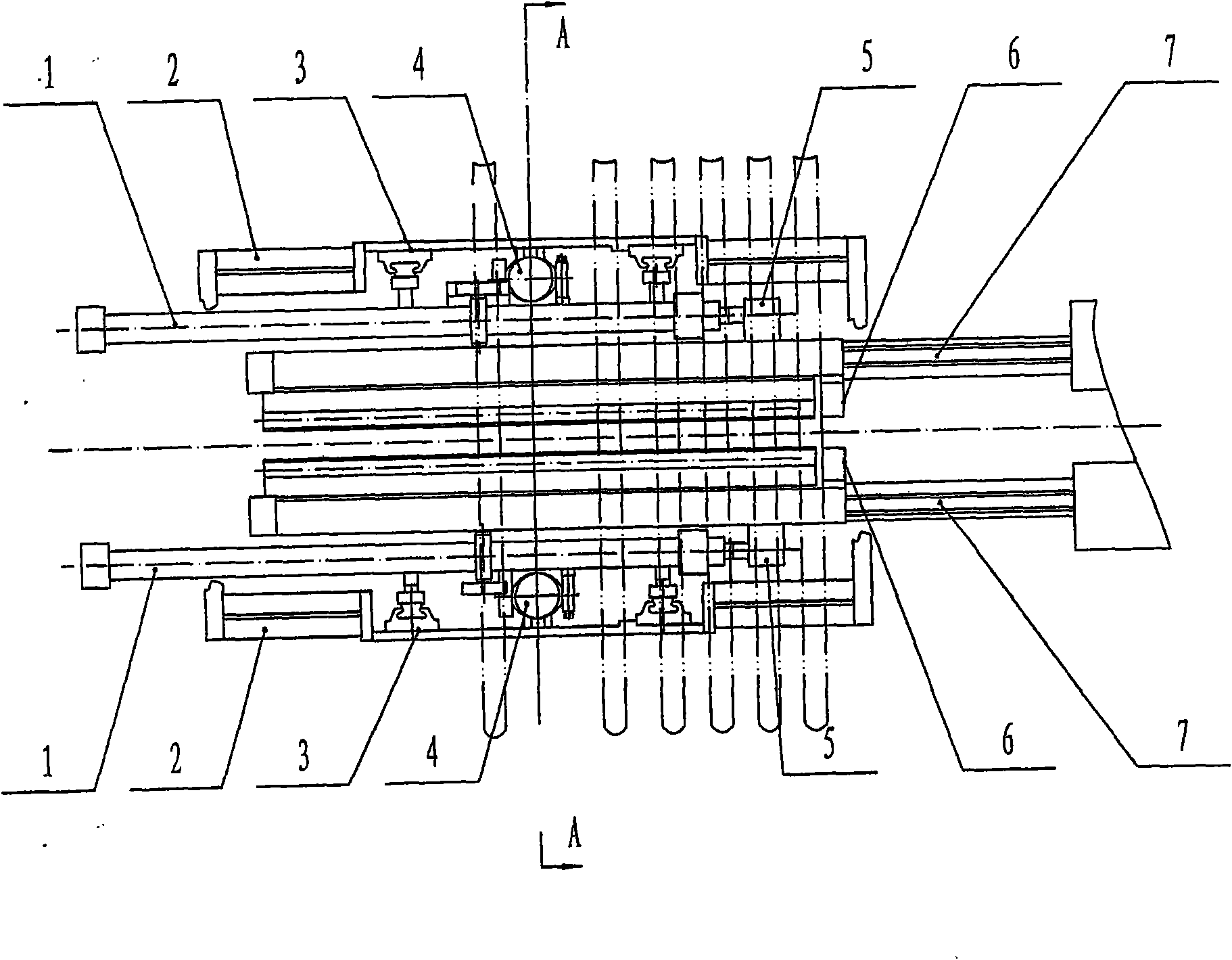
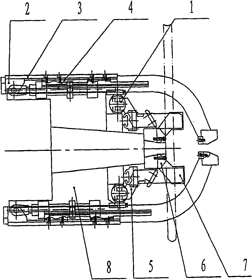
The invention relates to an abrasive wheel saw clamping mechanism which mainly realizes saw cutting and clamping of steel billet. The abrasive wheel saw clamping mechanism comprises a base (8), horizontal clamping oil cylinders (1), horizontal feeding brackets (5), horizontal linear guide rails (7), vertical clamping oil cylinders (4), vertical swaging brackets (2), vertical linear guide rails (3) and two chock blocks (6), wherein the horizontal clamping oil cylinders (1) are arranged the front side and the rear side of the upper part of the base (8); the horizontal linear guild rails (7) arearranged at the front side and the rear side of the upper part of the base (8); the horizontal feeding brackets (5) are arranged on the two horizontal linear guide rails (7), and are respectively articulated with piston rods of the two horizontal clamping oil cylinders (1); the vertical clamping oil cylinders (4) are arranged at both sides of the front and the rear of the lower part of the base (8); the vertical linear guide rails (3) are arranged at the front side and the rear side of the lower part of the base (8); the vertical linear guide rails (3) are arranged at the front side and the rear side of the lower part of the base (8); the vertical swaging brackets (2) are vertically arranged on the two vertical linear guide rails (3), and are respectively articulated with the piston rods of the two vertical clamping oil cylinders (4); and the two chock blocks (6) are respectively arranged on the front part and the rear part and are fixedly arranged at the middle of the top of the base(8). The invention can save space and has good sawing cutting effect.
Description
Grinding wheel saw clamping mechanism (1) Technical field The invention relates to a grinding wheel saw. It mainly realizes sawing and clamping of steel billets. The utility model belongs to the technical field of steel rolling auxiliary equipment. (2) Background technology Bars and profiles must be sawed after coming out of the rolling mill. Generally, shearing machine cutting, metal saw blade sawing or grinding wheel saw blade sawing are used. Using a shearing machine to cut rails with complex sections will cause the sheared section to be compressed and deformed. Therefore, in order to ensure the quality of the cross-section, it is necessary to use a sawing machine to cut off the special-shaped cross-section rolled pieces such as steel pipes and section steel. Compared with the metal saw, the grinding wheel saw can cut steel types of different materials, the vibration of the machine is small, and the sawing surface has the advantages of high finish. With the increas...
Claims
Login to View More Application Information
Patent Timeline
 Patent Type & AuthorityPatents(China)
IPC IPC(8): B24B27/06
Inventor刘成龙
OwnerJIANGYIN DONGCHEN MACHINERY MFG