
Electronic map aided inertial navigation method in GPS dead zone

An electronic map and inertial navigation technology, applied in the field of navigation, can solve the problems of poor reliability and low system accuracy, and achieve the effect of improving accuracy and reliability and improving positioning accuracy.

Inactive Publication Date: 2010-04-21
HARBIN INST OF TECH
View PDF0 Cites 39 Cited by
  • Summary
  • Abstract
  • Description
  • Claims
  • Application Information

AI Technical Summary

Problems solved by technology

[0003] In order to solve the problem of low system accuracy and poor reliability in the GPS failure area existing in the existing vehicle-mounted SINS / GPS integrated navigation system, the present invention proposes an electronic map-assisted inertial navigation method in the GPS blind area

Method used


Image

  • Electronic map aided inertial navigation method in GPS dead zone
  • Electronic map aided inertial navigation method in GPS dead zone
  • Electronic map aided inertial navigation method in GPS dead zone

Examples


specific Embodiment approach 1

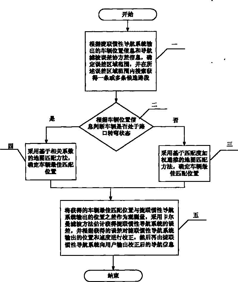
[0012] Specific implementation mode one: the specific process of a kind of electronic map-assisted inertial navigation method in the GPS blind area described in this implementation mode is:

[0013] Step 1: According to the vehicle position information output by the strapdown inertial navigation system and the navigation filter error covariance information, determine the error area range, and search and obtain one or more candidate road sections within the error area range;

[0014] Step 2: Determine whether the vehicle is turning at an intersection according to the vehicle location information, if not, go to step 3, if yes, go to step 4;

[0015] Step 3: Use the map matching method based on weighted recursion of matching degree to determine the best matching position of the vehicle, and then go to step 5;

[0016] Step 4: use the map matching method based on the correlation coefficient to determine the best matching position of the vehicle;

[0017] Step 5: The difference be...

specific Embodiment approach 2

[0056] Specific embodiment two: What this embodiment described is the method that the electronic map assisted inertial navigation method described in specific embodiment one in the GPS blind area is used in conjunction with the existing navigation method, and the specific method is:

[0057] To judge the validity of GPS, when GPS is valid, use the combination of SINS / GPS for navigation, use the difference between the position and speed information provided by GPS and the position and speed information of SINS as the observation, and estimate the error of SINS by Kalman filter method, Feedback correction of the position, velocity and attitude angle of SINS, the specific process is:

[0058] First, establish the mathematical model of SINS / GPS integrated navigation, including system equations and measurement equations.

[0059] The system equation is the SINS error equation ignoring the height channel:

[0060] X · 1 ...


PUM


Abstract

The invention discloses an electronic map aided inertial navigation method in a GPS dead zone, relates to the technical field of navigation and solves problems of low system precision and poor reliability in a GPS failure zone where the prior vehicle-mounted SINS / GPS integrated navigation system is positioned. The method comprises the following steps of: firstly, determining an error area range matching with the map and searching for a candidate road section; secondly, judging whether a vehicle is in a crossing turning state or not, if the vehicle is not in the crossing turning state, using a matching degree weighting recursion-based map matching method to determine the best matching position of the vehicle, and if the vehicle is in the crossing turning state, using a related coefficient-based map matching method to determine the best matching position of the vehicle; and finally, using the best matching position of the vehicle, which is obtained by map matching, to aid a strapdown inertial navigation system to combine and correct position. By combining the prior navigation method, the method of the invention effectively improves the precision and the reliability of the vehicle-mounted SINS / GPS integrated navigation system.

Description

technical field [0001] The invention relates to the technical field of navigation, in particular to an electronic map-assisted inertial navigation method in a GPS blind area. Background technique [0002] Strapdown Inertial Navigation System (SINS, Strapdown Inertial Navigation System), referred to as SINS, referred to as inertial navigation system, is a completely autonomous navigation system, which can continuously provide various navigation parameter information such as the position, speed, orientation and attitude of the carrier, It can track the rapid maneuvering movement of the carrier, and has good stability in a short time. However, the error of inertial navigation accumulates over time, and it cannot work alone for a long time, and must be constantly calibrated. Global Positioning System (GPS, Global Positioning System), referred to as GPS, is currently the most widely used satellite navigation and positioning system. The most widely used is a combination system c...

Claims


Application Information

Patent Timeline
Patent Type & Authority Applications(China)
IPC IPC(8): G01C21/30
Inventor 徐田来崔平远崔祜涛徐敏强
Owner HARBIN INST OF TECH
Learn More