Device and method for testing performance of two-phase flow drag reducer

A test device and technology of drag reducer, which is applied in the direction of DC flow characteristic measurement, etc., can solve the problem of low drag reduction rate of drag reducer

Inactive Publication Date: 2010-04-21
XI AN JIAOTONG UNIV
View PDF0 Cites 18 Cited by
  • Summary
  • Abstract
  • Description
  • Claims
  • Application Information

AI Technical Summary

Problems solved by technology

Some research results show that the drag reduction efficiency of drag reducers on two-phase flow is higher than that of single-phase flow, which indicates that there may be a secondary drag re

Method used


Image

  • Device and method for testing performance of two-phase flow drag reducer
  • Device and method for testing performance of two-phase flow drag reducer
  • Device and method for testing performance of two-phase flow drag reducer

Examples


Embodiment 1

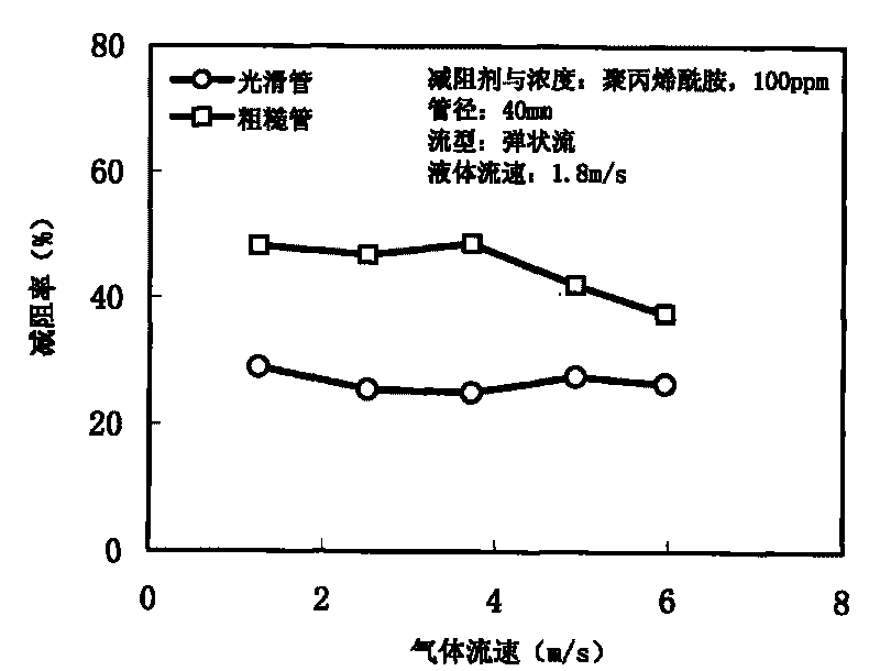
[0039] Example 1 Performance test of gas-liquid two-phase flow drag reducer

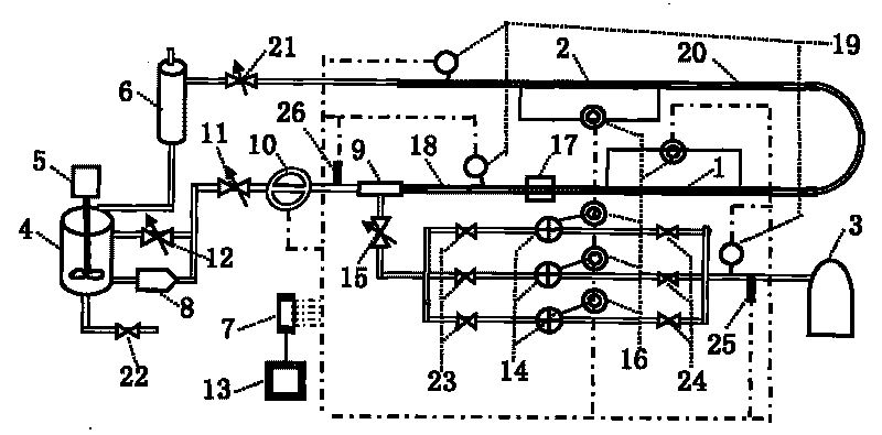
[0040] (1) Add the solvent phase of the drag reducing agent to the liquid storage container 4 first, and do not add the drag reducing agent at this time, and wait to test the frictional resistance characteristics of the two-phase flow without the drag reducing agent.

[0041] (2) Turn on the screw pump 8 and the air source 3 in sequence. Open the pressure regulating valve 21, the liquid main pipeline regulating valve 11 and the bypass regulating valve 12 in sequence, and through the joint adjustment of the liquid main pipeline regulating valve 11 and the bypass regulating valve 12, the liquid flow rate is kept within the range of 0.6-3m / s. A stable value, in this embodiment, this stable value is 1.8m / s. Select the size of the gas orifice plate according to the gas flow rate, and open the ball valves before and after the selected orifice plate. Then open the gas regulating valve 15, through the regu...

Embodiment 2

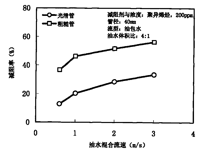
[0048] Example 2 Performance test of oil-water two-phase flow drag reducer

[0049] (1) Add oil and water in a certain proportion to the liquid storage container 4 and use the agitator 5 to fully mix the two phases of oil and water. At this time, no drag reducing agent is added. In this embodiment, the volume ratio of oil to water is 4:1.

[0050] (2) Close the ball valves 24, 15 before and after the gas regulating valve 15 and the gas orifice. Turn on the screw pump 8, open the pressure regulating valve 21, the liquid main pipeline regulating valve 11 and the bypass regulating valve 12 in sequence, and gradually change the flow rate of the oil-water mixture through the linkage regulation of the liquid main pipeline regulating valve 11 and the bypass regulating valve 12 , to test the frictional resistance of the oil-water two-phase flow in the smooth pipe test section and the rough pipe test section respectively.

[0051] (3) Obtain a set of frictional resistance data DR at ...


PUM


Abstract

The invention discloses a device and a method for testing the performance of a two-phase flow drag reducer, which are used for testing the drag reduction performance of the drag reducer for reducing the two-phase flow frictional resistance of a horizontal pipe under the condition of different gas speeds, liquid speeds, drag reducer concentrations and the like. A smooth pipe horizontal test section and a rough pipe horizontal test section with the same pipe diameter are adopted to form a loop test device, and the method for testing the performance of the two-phase flow drag reducer comprises the following basic steps: testing the drag reduction performance of the drag reducer when a solvent phase and a non-solvent phase of the drag reducer are in mixed flow in a horizontal smooth pipe; testing the drag reduction performance of the drag reducer when the solvent phase and the non-solvent phase of the drag reducer are in mixed flow in a horizontal rough pipe under the condition of the same fluid flow rate, two-phase flow pattern, drag reducer concentration and the like as that in the horizontal smooth pipe; and representing the test result of the performance of two-phase flow drag reducer by taking the drag reduction rate of the drag reducer to the two-phase flow in the smooth pipe as a lower boundary and taking the drag reduction rate of the drag reducer to the two-phase flow in the rough pipe as an upper boundary.

Description

technical field [0001] The invention relates to a device and a method for testing the drag reduction performance of drag reducers on two-phase flow frictional resistance, which is used for testing the drag reduction performance of various drag reducers in two-phase flow. Background technique [0002] The use of drag reducing agent to reduce the frictional resistance of pipe flow is one of the common drag reduction technologies. Drag reducers are a class of chemical substances soluble in liquids, and are usually divided into two categories: water-soluble drag reducers and oil-soluble drag reducers. The most commonly used drag reducers are polymers. Studies have shown that a small amount of polymer drag reducer can significantly reduce the frictional resistance of liquid flowing in the pipeline, and the drag reduction rate can reach 50%, even as high as 70% to 80% in some cases. The successful application of polymeric drag reducers in water or oil transportation has brought ...

Claims


Application Information

Patent Timeline
IPC IPC(8): G01N11/04
Inventor 刘磊李操鲍青波周芳德
Owner XI AN JIAOTONG UNIV
Why Eureka
Try Eureka