Rotary type winding machine of bicycle motor

A technology for electric motors and bicycles, applied in the field of winding machines, can solve the problems of complex structure, low efficiency and high cost, achieve broad market prospects, overcome the effects of complex structure and low cost

Inactive Publication Date: 2010-04-21
帅立国
View PDF1 Cites 5 Cited by
  • Summary
  • Abstract
  • Description
  • Claims
  • Application Information

AI Technical Summary

Problems solved by technology

[0009] Technical problem: In order to realize the winding of high-density multi-slot bicycle motor windings, the present invention is mainly suitable for winding cylindrical windings for traditional winding machines and the existing patented bicycle motor winding machines have complex structure, high cost and low efficiency. To solve the low-level problem, a rotary bicycle motor winding machine is provided. The winding machine has a simple structure and low cost, and can effectively solve the problem that the existing bicycle motor cannot be automatically wound.

Method used


Image

  • Rotary type winding machine of bicycle motor
  • Rotary type winding machine of bicycle motor
  • Rotary type winding machine of bicycle motor

Examples


Embodiment Construction

[0025] The technical solution of the present invention will be further described below in conjunction with the accompanying drawings and embodiments.

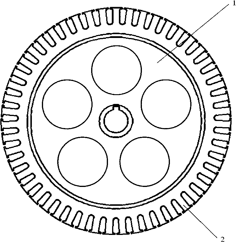
[0026] figure 1 It is the target application object of the present invention. Wherein there are bicycle motor iron core 1, support frame 2. Wherein the support frame 2 is evenly distributed on the outer periphery of the motor iron core 1, and the two form a whole, which is the support for the coil to be wound.

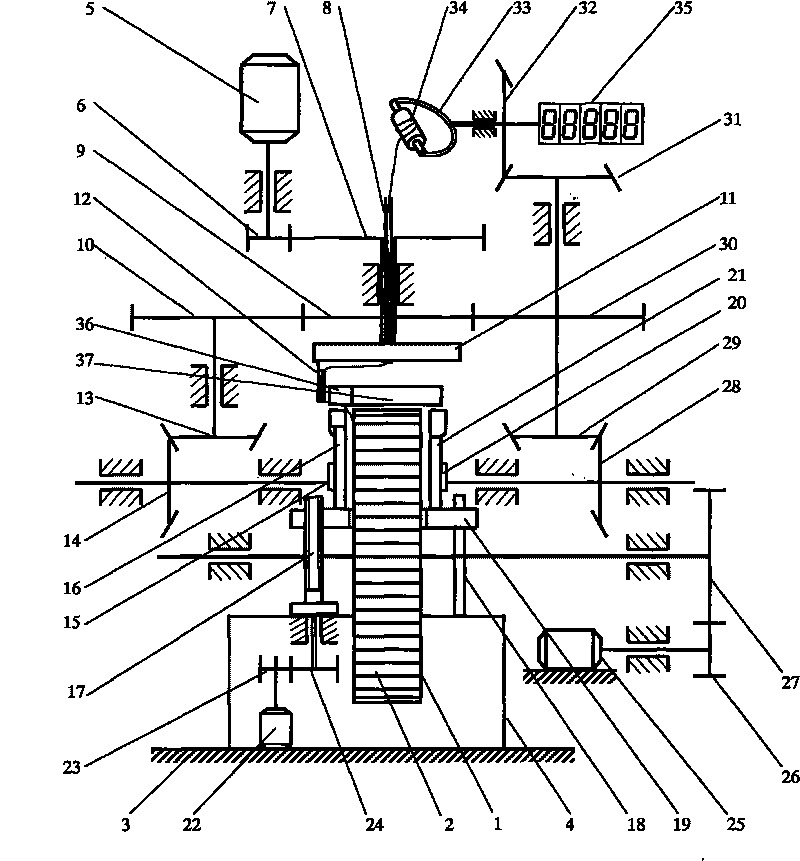
[0027] figure 2It is a schematic diagram of the mechanical principle of the present invention. Wherein there are bicycle motor iron core 1, support frame 2, support body 3, support frame 4, main motor 5, transmission wheel 6, transmission wheel 7, lead pipe 8, transmission wheel 9, transmission wheel 10, rotary disk 11, Bobbin 12, drive wheel 13, drive wheel 14, left cam 15, left crimping frame 16, left screw 17, guide rod 18, support frame 19, right cam 20, right crimping frame 21, motor 22, drive wheel 23, trans...


PUM


Abstract

The invention is an automatic winding machine used for winding a winding of a bicycle motor. The winding machine mainly comprises the functional modules of a rotary winding motion mechanism, a wire pressing motion mechanism, a wire pressing supporting rack height adjusting mechanism, a bicycle motor iron core rotating mechanism, a counting mechanism, a tensioning mechanism and the like, wherein the most remarkable characteristics of the winding machine is that: two opposite circular arc-surface explorators are used for leading enamelled wires to a groove, and the uniform winding is realized by using the wire pressing mechanism to adjust the height of a winding coil. When the enamelled wires are wound around a supporting rack (2), because of the blocking of the circular arc-surface explorators of a back wire rack (36) and a front wire rack (37), the enamelled wires are limited and led to a wire groove between the supporting racks; and when the enamelled wires are wound to the outside of the left side (or right side) of the wire groove, a left wire pressing rack (16)(or right wire pressing rack (21)) is driven by a cam (15) (or a cam (20)) to easily press down the enamelled wires to a proper height. By reasonably adjusting the rotary speed of a left screw rod (17), the heights of the wire pressing supporting racks can be gradually adjusted, so that the uniform winding of the coil is realized, and the winding density of the enamelled wires can be dynamically adjusted and controlled. In the winding process, an enamelled wire roller (34) rotates in the same direction as the winding direction, so that the torsional stress of the enamelled wires generated in the process of winding the coil can be released. The winding machine is characterized in simple structure, high efficiency, low cost and automatic counting, and can be widely used for winding the coil of the motor of the bicycle and the coil similar to the armature.

Description

technical field [0001] The invention relates to a winding machine for winding motor coils, in particular to a rotary bicycle motor winding machine capable of winding high-density multi-slot iron core coils. Background technique [0002] Motor rotors, especially the rotor cores of integrated motors such as electric bicycles and motorcycles, usually have various types and complex structures. At present, the most commonly used motors for electric bicycles are brushed toothless motors and brushless toothless motors. The difference between a brushed motor and a brushless motor is that a brushed motor is mechanically commutated by a carbon brush and a commutator, while a brushless motor senses a signal through a Hall element and is electronically commutated by a controller. [0003] There are many types of brushed toothless motors. Brushed toothless motors are mainly composed of rotor coils, stator magnets, left and right side covers, carbon brushes, commutators, motor shafts and ...

Claims


Application Information

Patent Timeline
Patent Type & Authority Applications(China)
IPC IPC(8): H02K15/08H02K15/085H02K15/09
Inventor 帅立国
Owner 帅立国
Why Eureka
Try Eureka