
Notching device with separated stator and rotor

A stator-rotor and punching technology is applied in the field of stator-rotor separation punching devices, which can solve the problems of large labor and high cost of stator blanking molding, and achieve the advantages of reducing labor intensity, reducing cost of parts, and improving work efficiency. Effect

Inactive Publication Date: 2010-04-28
WUXI NEW GREAT POWER ELECTRICAL MACHINE
View PDF5 Cites 6 Cited by
  • Summary
  • Abstract
  • Description
  • Claims
  • Application Information

AI Technical Summary

Problems solved by technology

[0005] The purpose of the present invention is to provide a punching die for separating the stator and rotor of the motor, which solves the problem that after the stator punching is punched, it is necessary to use a large press to separate the rotor punching, and then sort the rotor again, which requires a lot of labor. At the same time, it solves the problem of the stator blanking die The cost of molding is high, and a large press is required to produce

Method used


Image

  • Notching device with separated stator and rotor
  • Notching device with separated stator and rotor

Examples


Embodiment Construction

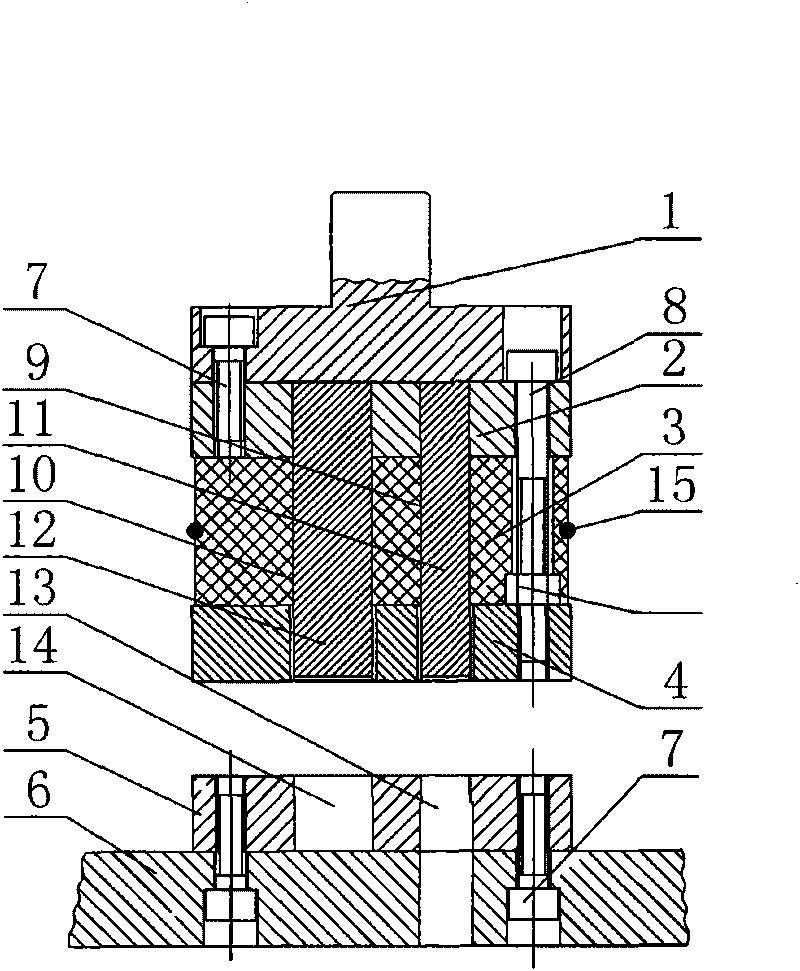
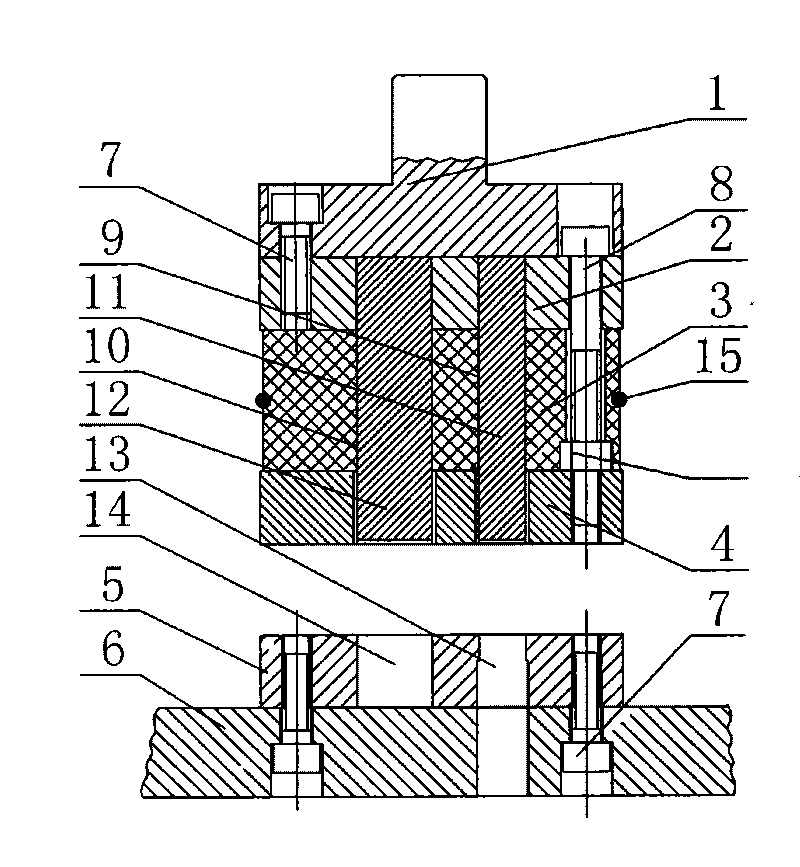
[0015] Such as figure 1 As shown, the stator-rotor separation punching device according to the present invention includes an upper die handle 1, a fixed plate 2 at the lower part of the die handle 1, a discharge plate 4, and a rubber pad 3 between the fixed plate 2 and the discharge plate 4 , the lower mold 5 and the lower template seat 6 at the bottom, the lower mold 5 is fixed on the lower template seat 6 by the fastening screw 7, the mold handle 1 is fixed on the fixed plate 2 by the fastening screw 7, and the fixed plate 2 and the discharge plate The stator slot 9 and the stator-rotor separation cutting slot 10 are respectively opened on the 4, and the stator slot 13 and the stator-rotor separation cutting slot 14 are respectively provided on the lower die 5 corresponding to the stator slot 9 and the stator-rotor separation cutting slot 10. The rotor separation cutting slot hole 14 passes through the lower template seat 6, and inserts the stator slot punch 11 and the stato...


PUM


Abstract

The invention relates to a notching device with a separated stator and a rotor, which comprises a die shank on the upper part, a fixing plate on the lower part of the die shank, an unloading plate, a rubber pad between the fixing plate and the unloading plate, a lower die on the lower part and a lower die plate base, wherein the whole device is arranged on a notching press to notch a stator slot and simultaneously separate a rotor punching and an excircle stator punching, and a ratchet wheel on the notching press rotates a round to finish a stator notching and a rotor separation. Three male dies are arranged in a male die fixing plate, the unloading plate and the male dies are in clearance fit by adopting interference fit, two jacking blocks are arranged in two separated holes of a female die, and a spring is used for finishing motions. The notching of a stator slot and the separation of the rotor punching are finished on a die without a separating die and a press machine for separating the rotor sheet, so the labor intensity is reduced and the working efficiency is improved; simultaneously, a blanking die of the stator excircle is not needed so that the manufacturing cost of the stator punching is greatly reduced; moreover, the excircle and the inside diameter of the stator are finished on the same die so that the requirement on the coaxiality is sufficiently ensured.

Description

technical field [0001] The invention relates to a stamping and slotting die for separation of stator and rotor of a motor, which is a stator and rotor separation punching device capable of completing notching of the motor stator, separation of the rotor and stamping of the outer circle of the stator. Background technique [0002] At present, the commonly used motor stator punching die is punched separately. After punching by the punching machine, the rotor separation die is used to separate the rotor slices by a large press, and then the rotor punching and stator punching are manually arranged, which requires a lot of labor. , need to use a large press, and the efficiency is very low. [0003] At the same time, the outer circle of the commonly used stator punching is punched by a large press through the blanking die. The coaxiality of the inner and outer circles of the electronic stator punching is high, and the manufacturing accuracy of the blanking die is high. , so the c...

Claims


Application Information

Patent Timeline
Patent Type & Authority Applications(China)
IPC IPC(8): B21D28/14B21D45/04
Inventor 徐荣祖马天龙
Owner WUXI NEW GREAT POWER ELECTRICAL MACHINE
Learn More