High-speed LDPC code coder and coding method thereof

A technology of LDPC codes and encoders, which is applied in the field of high-speed LDPC codes and encoders, and can solve the problems of increased computational and storage complexity, impracticality, and inability to guarantee the sparsity of the generator matrix.

Inactive Publication Date: 2010-04-28
SHANDONG UNIV
View PDF0 Cites 21 Cited by
  • Summary
  • Abstract
  • Description
  • Claims
  • Application Information

AI Technical Summary

Problems solved by technology

Although the parity check matrix of LDPC codes is very sparse, the sparsity of its generation matrix cannot be guaranteed, which may greatly increase the complexity of encoding operations and storage; and if the spars

Method used


Image

  • High-speed LDPC code coder and coding method thereof
  • High-speed LDPC code coder and coding method thereof
  • High-speed LDPC code coder and coding method thereof

Examples


Embodiment 1

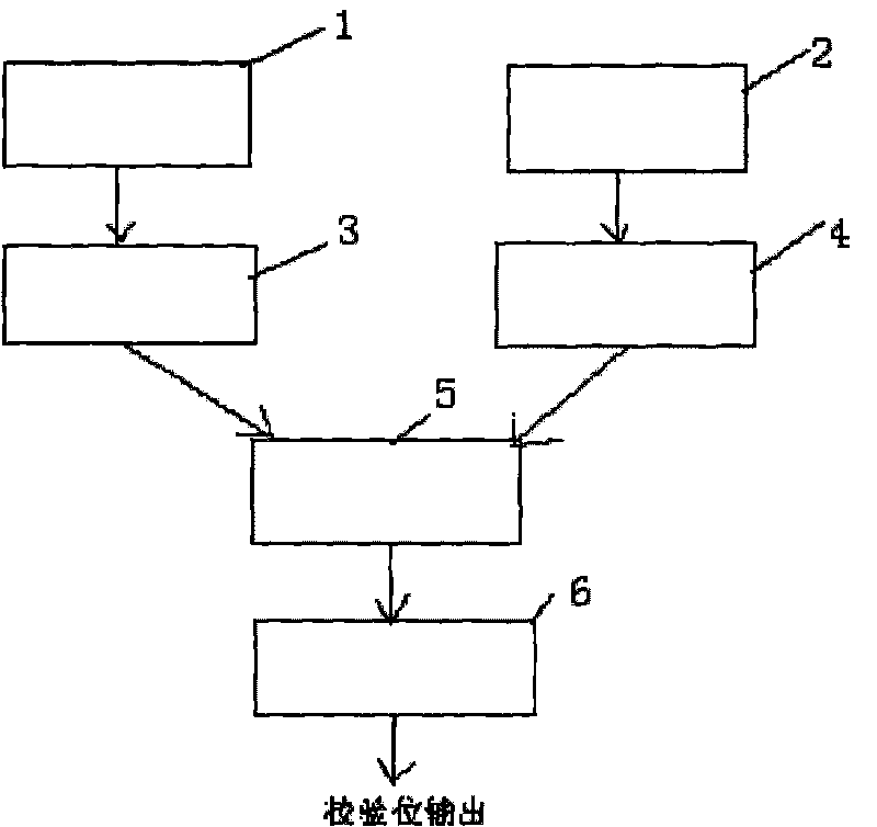
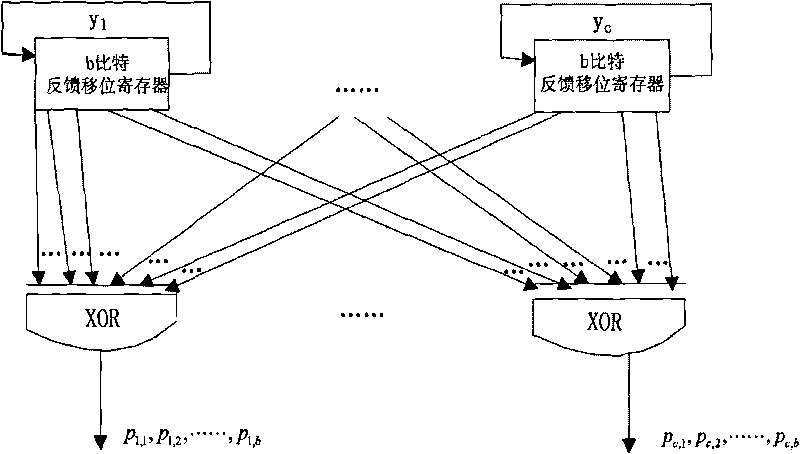
[0085] Such as figure 1As shown, a high-speed LDPC code encoder includes primary encoding circuits 1 and 2, secondary encoding circuit 6, temporary storage modules 3 and 4 and control module 5, primary encoding circuits 1, 2 and secondary encoding circuit 6 It contains a feedback shift register and an exclusive OR gate, and the first-level encoding circuits 1 and 2 obtain intermediate vectors according to the check matrix and information bits, and the temporary storage modules 3 and 4 are register groups, which are characterized in that two-way first-level encoding circuits 1, 2 The output terminal of 2 is connected to the register input terminals in the two temporary storage modules 3 and 4, and the output terminal of the registers in the temporary storage modules 3 and 4 passes through the control module 5 and the input terminal of the feedback shift register of the secondary encoding circuit 6 connected, the secondary encoding circuit 6 obtains the check bit according to th...

Embodiment 2

[0088] A method of encoding using the above encoder, such as Figure 1-5 As shown, the steps are as follows:

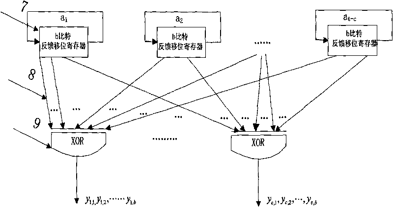
[0089] 10. In the first clock cycle, the control module 5 controls the primary encoding circuit ① to start working, the primary encoding circuit ② and the secondary encoding circuit wait, and the It is known that at this time, it is equivalent to l=1, and y is obtained through the calculation of the first-level encoding circuit ① 1,1 ,y 2,1 ,...y c,1 , and store these c bits into the 0th bit of the feedback shift register of c of the temporary storage module 3;

[0090] 11. In the second clock cycle, the control module 5 controls the primary encoding circuit ① to stop working, the primary encoding circuit ② starts to work, and the primary encoding circuit ② calculates y 1,2 ,y 2,2 ,...y c,2 , respectively stored in the first bit of each feedback shift register in the temporary storage module 4;

[0091] 12. In the third clock cycle, the first-level encoding ci...


PUM


Abstract

The invention relates to a high-speed LDPC code coder and a coding method thereof, belonging to the technical field of mobile communication channel coding. The coder comprises a primary and a secondary coding circuits, a temporary storage module and a control module. The primary and the secondary coding circuits each include a feedback shift register and an exclusive or gate. The primary coding circuit may obtain an intermediate vector based on a check matrix and an information bit. The temporary storage module is a register bank. The coder is characterized in that the output ends of two branches of primary circuits are connected with the register input ends of two branches of temporary storage modules; the output end of the register in the temporary storage module after passing through the control module is connected with the input end of the feedback shift register of the secondary coding circuit; and the secondary coding circuit obtains a check bit based on the intermediate vector and the check matrix. The method realizes coding by directly using the information of the check matrix, wherein the intermediate vector is obtained firstly and then the check bit is obtained based on the intermediate vector and the information in the check matrix. The method has high coding efficiency and can be widely applied to the technical field of the mobile communication channel coding.

Description

1. Technical field: [0001] The invention relates to a high-speed LDPC code encoder and its encoding method, belonging to the technical field of mobile communication channel encoding. 2. Background technology: [0002] With the rapid development of wireless Internet multimedia communication, wireless communication systems have higher and higher requirements for speed and reliability. At present, the theoretical research on LDPC codes has become mature, and both international and domestic research focuses on the realization of codecs. The focus of research is how to increase the efficiency of codecs as much as possible under the existing device conditions. . my country's 3G construction is in full swing, and research on 4G has already begun. The key technologies of the fourth-generation mobile communication of MIMO+OFDM+LDPC pose a severe test to universities and research fields. [0003] LDPC codes have been widely used in deep space communication, optical fiber communicati...

Claims


Application Information

Patent Timeline
IPC IPC(8): H03M13/11
Inventor 马丕明李士忠
Owner SHANDONG UNIV
Why Eureka
Try Eureka