
Friction force controllable bracket

A friction and controllable technology, applied in brackets, medical science, dentistry, etc., can solve problems such as loss of bracket shaft inclination and torque angle, inconvenient replacement of chain elastic rings, and difficulty in controlling the position of teeth. To achieve the effect of reducing friction, accelerating movement, and reducing movement

Inactive Publication Date: 2010-05-05
CHONGQING MEDICAL UNIVERSITY
View PDF0 Cites 2 Cited by
  • Summary
  • Abstract
  • Description
  • Claims
  • Application Information

AI Technical Summary

Problems solved by technology

[0004] But the self-locking bracket appliance of above-mentioned structure has the following deficiencies: one, although the frictional force reduces, but has brought the problem that is difficult to control tooth position; Sometimes it is still necessary to use the ligature wire to ligate the arch wire in the mesial or far of the bracket through the vertical groove to correct and prevent the inclination and rotation of the teeth. The torque angle will be lost, and sometimes necessary compensation must be done on the arch wire; 3. It is inconvenient to replace the chain elastic ring, and the self-locking bracket elastic ring must be installed before the arch wire is in place, not the arch wire After being in place, the arch wire must be removed when replacing the chain elastic ring, which will bring inconvenience to clinical operations; 4. It is difficult to achieve complete alignment; 5. Due to the low friction, the arch wire is easy slip in groove

Method used


Image

  • Friction force controllable bracket
  • Friction force controllable bracket
  • Friction force controllable bracket

Examples


Embodiment Construction

[0019] The present invention will be further described in detail below in conjunction with the drawings and specific embodiments.

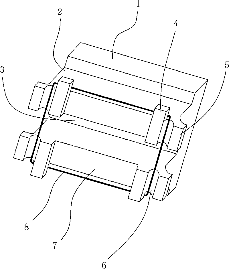
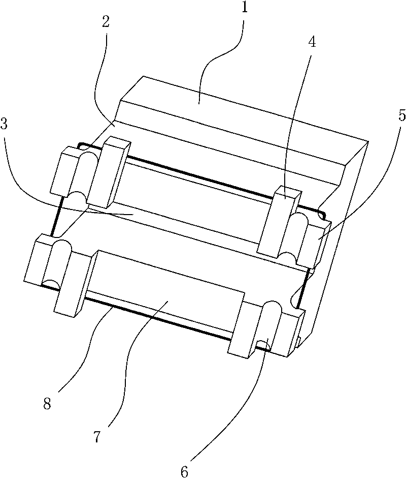
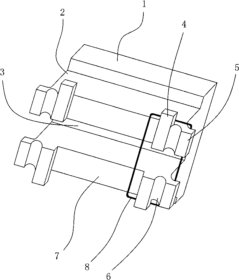
[0020] figure 1 It is a schematic diagram of the structure of the present invention in the first state of use. As shown in the figure, a friction controllable bracket includes a base plate 1 and two bracket bodies 2 fixedly arranged on the base plate 1 in parallel and opposite; An archwire groove 3 at a certain angle to the bottom plate 1 is formed between the bracket bodies 2; both ends of the bracket body 2 are respectively provided with protruding directions opposite to the archwire groove 3 Gingival wings 4 and lateral wings 5 ​​protruding to the side; two The gingival wings 4 are located on the inner side of the two side wings 5 ​​and extend out of the bracket body 2 in a direction parallel to the bottom plate 1; the side wings 5 ​​extend out of the bracket body 2 in a direction parallel to the bottom plate 1; A ligature groove 6 is formed bet...


PUM


Abstract

The invention discloses a friction force controllable bracket which comprises a base bottom plate and two bracket bodies opposite to the base bottom plate, wherein an arc wire groove is formed between the two bracket bodies, two ends of the bracket bodies are respectively provided with foot wings protruding towards the opposite direction of the arc wire groove and side square wings protruding towards the side direction of the arc wire groove, and the two foot wings are positioned at the inner sides of the two side square wings and extend to form a bracket body along the opposite direction of the arc wire groove. By selecting different parts for ligaturing, the positive pressure of the ligaturing to an arc wire is changed, thereby achieving the function of regulating the friction force. Only the foot wings are ligatured to enable the positive pressure to be zero, which reduces the friction resistance and accelerates the movement of teeth and lowers the tissue injury, thereby playing a similar role of a self-locking bracket. The side square wings also can be tightly ligatured, which increases the friction force of individual teeth and the arc wire and selectively controls the movement of the individual teeth. The foot wing at one side and the side square wings are ligatured, which can change the teeth torsion and accurately regulates the tooth position.

Description

Technical field [0001] The invention relates to a bracket appliance, in particular to a friction control type bracket with a flexible ligation method. Background technique [0002] Dental friction controllable brackets are an important part of orthodontic fixed appliances. Orthodontic clinical brackets are composed of a fixed base plate and a bracket body. The bracket body has an archwire groove and ligation wings. The base plate is fixed on the tooth surface, and the archwire passes through the archwire groove and passes The ligation wings are fixed with the brackets. During the orthodontic treatment of the dentition, the corrective force of the arch wires is transmitted to the teeth through the brackets, so that the teeth can move as expected. [0003] Since the direct bonding technique of brackets was used in orthodontics in the 1950s, friction-controllable brackets have been widely used. The traditional friction-controllable brackets have high friction with the arch wire when...

Claims


Application Information

Patent Timeline
Patent Type & Authority Applications(China)
IPC IPC(8): A61C7/14A61C7/32
Inventor 王胜国
Owner CHONGQING MEDICAL UNIVERSITY
Learn More