
Floating impeller serial hydraulic turbine

A water turbine and floating technology, applied in mechanical equipment, engine components, machines/engines, etc., can solve the problems of large diameter of a single set of blades, inconvenient maintenance and management, and low power of the device, so as to improve safety, facilitate maintenance and Effects of improved management and utilization efficiency

Inactive Publication Date: 2010-05-05
余炜彬
View PDF4 Cites 18 Cited by
  • Summary
  • Abstract
  • Description
  • Claims
  • Application Information

AI Technical Summary

Problems solved by technology

But it also has the following problems: 1, the blade water turbine is a single set of blade structure, so that the power of the device is smaller thereupon, and cannot satisfy people's needs
2. The diameter of the single-set blade structure is large, so it cannot be used in places where the water flow is shallow, and the scope of use is small
3. There is a problem of inconvenient maintenance and management

Method used


Image

  • Floating impeller serial hydraulic turbine
  • Floating impeller serial hydraulic turbine
  • Floating impeller serial hydraulic turbine

Examples


specific Embodiment 1

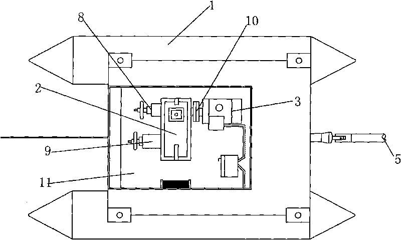
[0027] Figure 1 to Figure 6 Constitute the specific embodiment 1 of the present invention.

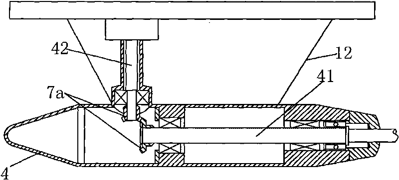
[0028] refer to figure 1 , figure 2 and image 3 , the present embodiment includes a floating body 1, a transmission gearbox 2 arranged on the floating body 1, a generator 3, a bevel gearbox 4 arranged at the bottom of the floating body, a transmission shaft 5 and an impeller group 6; the impeller group 6 includes two The serial shafts 61 connected to each other are provided with three impellers 63; one end of the transmission shaft 5 is connected to the serial shaft 61 at one end of the impeller group 6 through a universal coupling, and the other end is connected to the bevel gear box 4 The input shaft 41 of the bevel gear box 4 is connected to the input shaft 41 of the bevel gear box 4 with the vertical output shaft 42 through the bevel gear 7; The high speed shaft 22 is connected with the input shaft of the motor 3 . The tandem shaft 61 is a hollow tube that is connected with...

specific Embodiment 2

[0034] The feature of this embodiment is that the brake 8 is an electro-hydraulic block brake. Others are the same as in Example 1.

specific Embodiment 3

[0035] The feature of this embodiment is: the anti-rotation device 9 is an electrically controlled anti-rotation device. Others are identical with specific embodiment 1 or 2.

[0036] Other examples:


PUM


Abstract

The invention relates to a floating impeller serial hydraulic turbine which is characterized by comprising a floating body (1), a variable-speed gear box (2), a generator (3), a bevel gear box (4), a transmission shaft (5) and an impeller group (6). The impeller group (6) comprises a plurality of shafts (61) which are connected with each other in series, wherein each shaft (61) is provided with aplurality of impellers (62); one end of the transmission shaft (5) is connected with the shafts (61) which are arranged on one end of the impeller group (6) through a universal coupling, and the other end is connected with the input shaft (41) of the bevel gear box (4); the input shaft (41) of the bevel gear box (4) is connected with a vertical output shaft (42) through a bevel gear (7a); the vertical output shaft (42) is connected with the low-speed shaft of the variable-speed gear box (2) through the bevel gear (7b); and the high-speed shaft (22) of the variable-speed gear box (2) is connected with the input shaft of a motor (3). The invention has the advantages of high reliability, long service life and wide application range.

Description

technical field [0001] The invention relates to a water turbine, especially a floating impeller series water turbine that can be installed on the sea water surface of rivers and lakes with small drop for power generation or air compression, and belongs to ocean current energy, tidal current energy and river and river energy field of utilization technology. Background technique [0002] At present, the existing hydroelectric power station is built on the barrage, which collects and raises the water level of the river, and uses the water level drop during the discharge to drive the blade turbine of the power station to rotate, and then drives the generator to generate electricity. This kind of fixed power station has the advantage of large power generation, but this method still has huge investment, long construction period, and has a certain impact on shipping and ecological environment, and will also generate a large number of immigrants, thus limiting the development of hyd...

Claims


Application Information

Patent Timeline
IPC IPC(8): F03B13/00
Inventor 余炜彬
Owner 余炜彬
Learn More