Air and air energy recovery and ventilation device with defrosting and bypass air supplying functions

A technology of energy recovery and ventilation devices, which is applied in space heating and ventilation, ventilation systems, heating and ventilation control systems, etc., can solve the problem that the effect of cooling capacity to eliminate indoor loads is not utilized, and improve the annual operating time , reduce the recovery period, and reduce the effect of fresh air resistance

Inactive Publication Date: 2010-05-05
HARBIN INST OF TECH +1
View PDF1 Cites 18 Cited by
  • Summary
  • Abstract
  • Description
  • Claims
  • Application Information

AI Technical Summary

Problems solved by technology

[0003] The purpose of this invention is to solve the problem that the existing air and air energy recovery ventilation device has not been utilized in the t

Method used


Image

  • Air and air energy recovery and ventilation device with defrosting and bypass air supplying functions
  • Air and air energy recovery and ventilation device with defrosting and bypass air supplying functions
  • Air and air energy recovery and ventilation device with defrosting and bypass air supplying functions

Examples


specific Embodiment approach 1

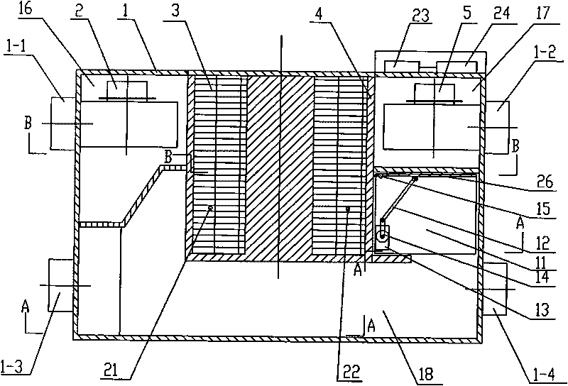
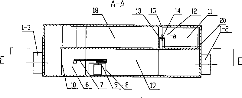
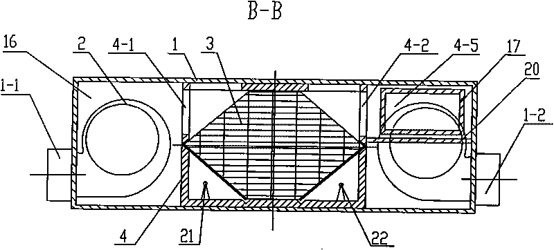
[0007] Specific implementation mode one: combine Figure 1-Figure 6 Describe this embodiment, the air and air energy recovery ventilation device of this embodiment includes a casing 1, an exhaust fan 2, a heat exchanger 3, a heat exchanger frame 4, a fresh air fan 5, and a bypass defrosting damper 6 and a power controller 24, the heat exchanger frame 4 is fixedly connected to the top surface, the left inner wall and the right inner wall of the casing 1, and the heat exchanger frame 4 divides the casing 1 into an exhaust chamber 16, Fresh air chamber 17, bypass air supply passage 18 and bypass defrosting air passage 19, the heat exchanger 3 is installed in the heat exchanger frame 4, and a side wall 4-6 of the heat exchanger frame 4 is provided with There is an exhaust vent 4-1 and a first air passage 4-3, and the other side wall 4-7 of the heat exchanger frame 4 is provided with a fresh air vent 4-2 and a second air passage 4-4, the exhaust fan 2 is installed in the exhaust c...

specific Embodiment approach 2

[0008] Specific implementation mode two: combination Figure 1-Figure 6 Describe this embodiment, the bypass defroster damper 6 of this embodiment is constituted by the first connecting rod 7, the first motor 8, the first slider 9, the first hinge 10 and the first baffle 25, the first A baffle plate 25 is arranged at the fresh air inlet 1-3 and is hinged with the casing 1 through the first hinge 10, one end of the first connecting rod 7 is hinged with the first baffle plate 25, and the other end of the first connecting rod 7 is hinged with the first connecting rod 7. A slider 9 is hinged, the first slider 9 is connected to the output shaft of the first motor 8, the first motor 8 is fixed on the bottom surface of the casing 1, and the power controller 24 is connected to the first motor through a wire. 8 connections. The first slider 9 is driven by the first motor 8 to rotate, and then drives the first connecting rod 7 to move, and the first connecting rod 7 drives the first ba...

specific Embodiment approach 3

[0009] Specific implementation mode three: combination Figure 7-Figure 12 Describe this embodiment, the air and air energy recovery ventilation device of this embodiment also includes fresh air temperature and humidity sensor 21, exhaust air temperature and humidity sensor 22 and temperature and humidity collection controller 23, and described fresh air temperature and humidity sensor 21 and described exhaust air The temperature and humidity sensor 22 is arranged in the heat exchanger frame 4, the temperature and humidity acquisition controller 23 is fixed on the top outer wall of the casing 1, the fresh air temperature and humidity sensor 21 and the exhaust air temperature and humidity sensor 22 are respectively It is connected to the temperature and humidity acquisition controller 23 through wires, and the temperature and humidity acquisition controller 23 is connected to the power controller 24 through wires. Such a design enables the present invention to automatically swi...


PUM


Abstract

The invention relates to an air and air energy recovery and ventilation device with defrosting and bypass air supplying functions, which belongs to an air and air energy recovery and ventilation device and aims at solving the problem that load in a cold energy eliminating chamber applying outdoor fresh air can not be utilized by the traditional air and air energy recovery and ventilation device in a transition season. The air and air energy recovery and ventilation device also comprises a bypass air supplying valve, wherein a fifth air passage hole is communicated with a bypass air supplying passage, one end of a baffle plate is arranged on the inner side wall of a casing and the other end is arranged on a heat exchange frame, a second baffle plate is arranged at the fifth air passage hole and is articulated with the heat exchange frame through a second hinge, one end of a second connecting rod is articulated with the second baffle plate and the other end is articulated with a second sliding block which is connected with an output shaft of a second motor in a transmission way, the second motor is fixedly arranged on the bottom end face of the baffle plate, and a power supply controller is connected with the second motor through a lead. The invention is used for recovering indoor heat and cold energy.

Description

technical field [0001] The invention relates to an air and air energy recovery ventilation device. Background technique [0002] Existing air and air energy recovery ventilation device has bypass defrosting function, as publication number is CN101509686A, and the Chinese invention patent application on August 19th, 2009 discloses a kind of " air with bypass defrosting function Ventilation device with air energy recovery", but this device has not been utilized in the transitional season to use the cooling capacity of the outdoor fresh air to eliminate the indoor load. Contents of the invention [0003] The purpose of this invention is to solve the problem that the existing air and air energy recovery ventilation device has not been utilized in the transition season to use the cooling capacity of the outdoor fresh air to eliminate the indoor load. Wind Functional Air with Air Energy Recovery Ventilator. [0004] The technical solution adopted by the present invention to so...

Claims


Application Information

Patent Timeline
IPC IPC(8): F24F3/147F24F13/10F24F11/02F24F7/007
Inventor 赵加宁刘京吴小冬陈泽民王明志
Owner HARBIN INST OF TECH
Why Eureka
Try Eureka