Heat sink section bar

A technology of profiles and heat dissipation parts, which is applied in heat exchange equipment, lighting and heating equipment, cooling/heating devices of lighting devices, etc., can solve problems such as unsatisfactory heat dissipation effects, and achieve improved heat dissipation effects and good heat dissipation effects

Inactive Publication Date: 2010-05-05
DONGGUAN KINGSUN OPTOELECTRONIC CO LTD
View PDF0 Cites 10 Cited by
  • Summary
  • Abstract
  • Description
  • Claims
  • Application Information

AI Technical Summary

Problems solved by technology

In any case, this solution is a passive heat dissipation mode. For some components with relatively large heat generation, the heat dissipation effect of this heat dissipation profile is not very ideal.

Method used


Image

  • Heat sink section bar
  • Heat sink section bar
  • Heat sink section bar

Examples


Embodiment Construction

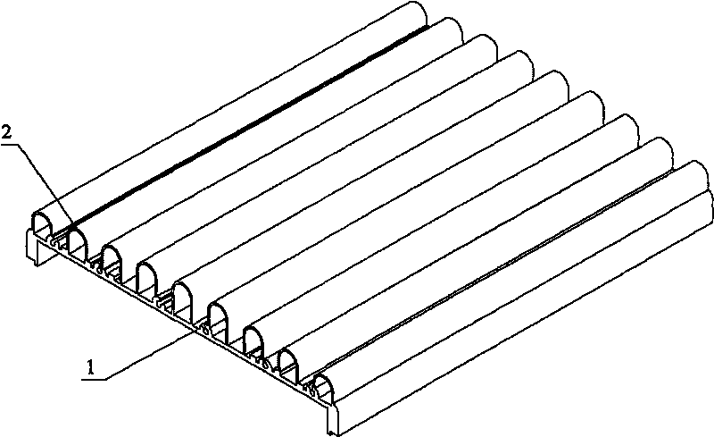
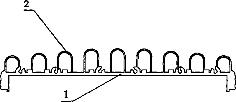
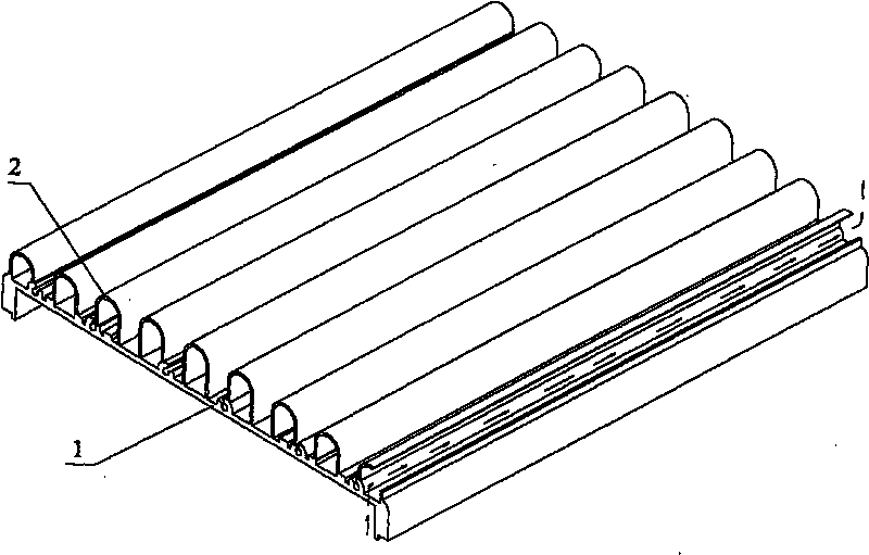
[0016] Such as figure 1 , figure 2 As shown, the heat dissipation profile of the present invention includes a heat dissipation substrate 1 and a heat dissipation element 2 arranged on the heat dissipation substrate 1. The heat dissipation element 2 is combined with the heat dissipation substrate 1 to form a tube shape, and the top of the section is arc-shaped. Compared with the straight fins, the top of the heat sink 2 section is arc-shaped, which increases the area of ​​the heat sink 2 in contact with the air. On the one hand, it can dissipate heat through radiation like the straight fins; on the other hand, when there is wind, when the wind direction When blowing along the axial direction of the cooling element, the heat dissipation effect will be better; and when the wind direction is perpendicular to the cooling element 2 (such as Figure 4 As shown), since the top of the cooling element 2 is arc-shaped, the wind will travel along this arc surface, and the air flow gener...


PUM


Abstract

The invention provides a heat sink section bar, relates to an engineering heat sink device, in particular to a heat sink section bar for accelerating heat sink of electronic products, and aims to solve the technical problem of improving the structure of the existing heat sink section bas to realize active heat sink of the section bars. The invention adopts the following technical scheme for solving the above technical problem: the heat sink section bar comprises a heat sink substrate and a heat sink piece arranged on the heat sink substrate, the heat sink substrate and the heat sink piece are combined to form a tube shape with the cross section of the top being arc-shape. As for further improvement, a bead can be axially arranged at the exterior of the heat sink piece, and moreover, a bead can be axially arranged at the interior of the heat sink piece. The invention improves structure, adds heat sink mode and enhances heat sink efficiency.

Description

technical field [0001] The invention relates to an engineering heat dissipation device, in particular to a heat dissipation profile for accelerating heat dissipation of electronic products. Background technique [0002] For heat dissipation profiles, the general solution is to add heat dissipation fins to the heat dissipation substrate. The heat dissipation fins are straight plates and distributed on one surface of the heat dissipation substrate (the other surface is equipped with components that need heat dissipation). A plurality of raised ribs and sunken grooves are arranged to make the sides of the cooling fins corrugated. [0003] This solution uses thermal radiation for passive heat dissipation, each heat dissipation fin exchanges heat with the air, and the ribs and grooves increase the heat dissipation area. If this kind of radiator is installed on the LED lamps used outdoors, the heat dissipation effect will be better when the wind direction is blowing along the hea...

Claims


Application Information

Patent Timeline
IPC IPC(8): F28F3/02F21V29/00F21Y101/02F21V29/70F21Y115/10
Inventor 卿笃碑
Owner DONGGUAN KINGSUN OPTOELECTRONIC CO LTD
Why Eureka
Try Eureka