
High-speed electric main shaft dynamic rigidity test device

A high-speed motorized spindle, dynamic stiffness technology, applied in the direction of machine gear/transmission mechanism testing, etc., can solve the problems of inability to meet the performance testing requirements of high-speed motorized spindle, inability to achieve non-destructive loading, difficult control and testing, etc., to achieve real-time measurement , stable dynamic loading, low difficulty effect

Inactive Publication Date: 2011-07-27
CHONGQING UNIV
View PDF0 Cites 0 Cited by
  • Summary
  • Abstract
  • Description
  • Claims
  • Application Information

AI Technical Summary

Problems solved by technology

If a traditional mechanical loading device is used to detect the dynamic performance of the electric spindle, although the device is simple and the cost is low, it is difficult to control and test, and the large amount of frictional heat and mechanical wear caused by the high-speed operation of the spindle cannot be used for non-destructive loading, and the loading cannot be realized Constant, which reduces the test accuracy and increases the difficulty of control
With the development of science and technology, the rotation speed of the spindle is getting higher and higher, making many traditional spindle performance testing techniques unable to meet the performance testing requirements of high-speed electric spindles

Method used


Image

  • High-speed electric main shaft dynamic rigidity test device
  • High-speed electric main shaft dynamic rigidity test device
  • High-speed electric main shaft dynamic rigidity test device

Examples


Embodiment Construction

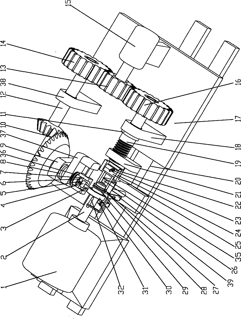
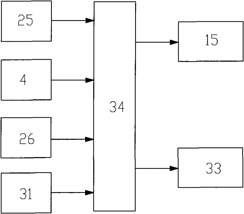
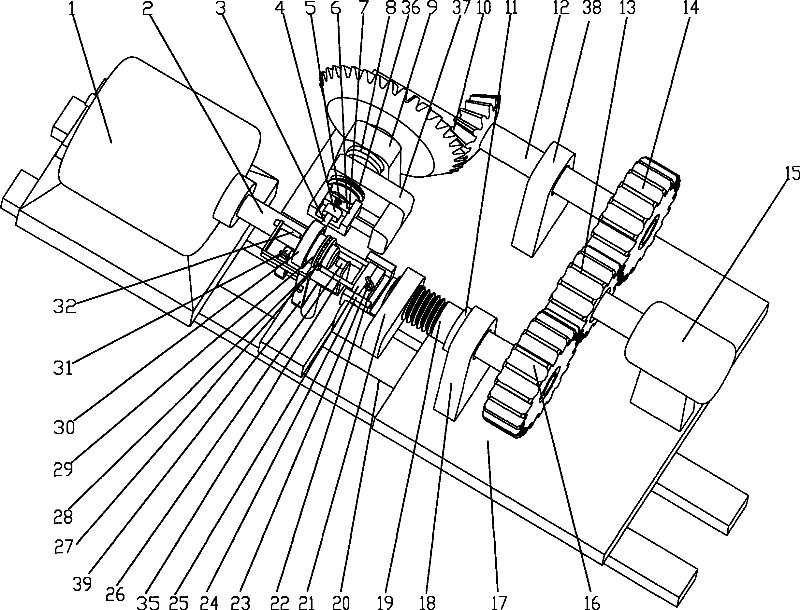
[0023] figure 1 It is a schematic diagram of the structure of the present invention, figure 2 It is the control schematic diagram of the present invention, as shown in the figure: the high-speed electric spindle dynamic stiffness testing device of this embodiment includes a base 17, a loading system and an automatic control unit 34;

[0024] The loading system includes an axial loading system, a radial loading system and a test rod 2 fixedly arranged on the high-speed electric spindle 1;

[0025] The outer circle of the test rod 2 is provided with a radial rolling bearing 30, and the loading end of the test rod 2 is provided with a plane rolling bearing 27;

[0026] Described axial loading system comprises axial loading rod 35 and axial loading driving system, and axial loading driving system comprises axial loading servo motor, axial loading driving screw rod 19 and axial loading driving nut 21, and described axial loading The drive screw 19 is in transmission cooperation ...


PUM


Abstract

The invention discloses a high-speed electric main shaft dynamic rigidity test device which comprises a base, a loading system and an automatic control unit, wherein the loading system comprises an axial loading system, a radial loading system and a test rod fixedly arranged on a high-speed electric main shaft; the excircle of the test rod is provided with a radial rolling bearing, and the loading end part of the test rod is provided with a plane rolling bearing; and the radial loading system and the axial loading system respectively load the test rod by the radial rolling bearing and the plane rolling bearing. The invention combines the high-speed rotation and static loading of the main shaft by the rolling bearing structure and acquires a loading value and a deforming value by a pressure sensor and a displacement sensor, and the control unit controls loading pressure according to the change of the loading value and the deforming value, thereby preventing the influence on test precision caused by friction heat generation and mechanical abrasion generated by mechanical contact when the high-speed electric main shaft is directly loaded in a state of high-speed running, realizing continuous and stable dynamic loading and real-time measurement of the high-speed electric main shaft and having high measurement precision.

Description

technical field [0001] The invention relates to a detection mechanism, in particular to a dynamic stiffness testing device for a high-speed electric spindle. Background technique [0002] High-speed electric spindle is the product of the rapid development of contemporary high-speed machining technology and theory. It not only satisfies high-speed machining, but also promotes the further development of high-speed machining technology theory. It is an emerging science and technology. Structurally, the driving motor is built in as a part of the rotating mass of the main shaft, and power transmission devices such as belts and gears are omitted, thereby effectively reducing the vibration and noise of the main shaft and making the speed of the main shaft the same as that of the driving motor. The rated speed is synchronized, and its control becomes precise and easy. However, when the spindle obtains a very high rotation speed, it also creates a complex mechanical, electrical, mag...

Claims


Application Information

Patent Timeline
Patent Type & Authority Patents(China)
IPC IPC(8): G01M13/02
Inventor 陈小安康辉民合烨毕江涛周明红陈文曲
Owner CHONGQING UNIV
Learn More