
High-precision +/-180 DEG digital phase distinguishing method and applying device thereof

A digital phase detection, high-precision technology, applied to circuits and electrical components that oscillate independently of each other, can solve the problems of complex implementation circuits, random errors in filling pulses, and high requirements, and achieve improved phase measurement accuracy, simple structure, and ease of use. effect achieved

Active Publication Date: 2012-02-29
善测(天津)科技有限公司
View PDF0 Cites 0 Cited by
  • Summary
  • Abstract
  • Description
  • Claims
  • Application Information

AI Technical Summary

Problems solved by technology

The multiplication method is based on two sinusoidal signals of the same frequency through a multiplier and a filter circuit to obtain a DC voltage, which is measured and displayed by a DC voltmeter; the vector method is based on the subtraction of two sinusoidal signals of the same frequency and equal amplitude to obtain the ( The phase difference value is obtained by the modulus of the vector difference proportional to the phase difference). The disadvantages of the above two methods are that the circuit is complex to realize, and the requirements for components are high, and the phase detection range is only ±90°
The numerical sampling method is to calculate the phase by continuously sampling a few points at equal time intervals. Its disadvantages are high requirements for software implementation, and the control of time intervals is relatively complicated.
The disadvantage of the gate circuit phase detection method is that it can only realize the phase detection within the range of 0-180°, and cannot distinguish the direction of the signal; the disadvantage of the trigger phase detection method is that there is a random error within one cycle of the filling pulse

Method used


Image

  • High-precision +/-180 DEG digital phase distinguishing method and applying device thereof
  • High-precision +/-180 DEG digital phase distinguishing method and applying device thereof
  • High-precision +/-180 DEG digital phase distinguishing method and applying device thereof

Examples


Embodiment Construction

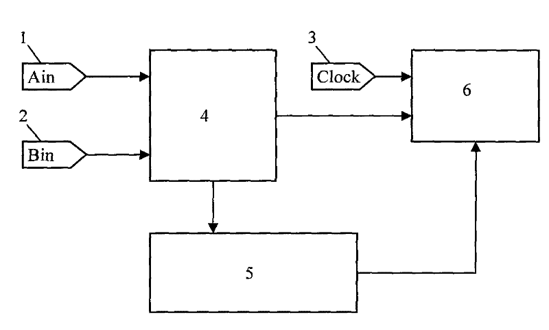
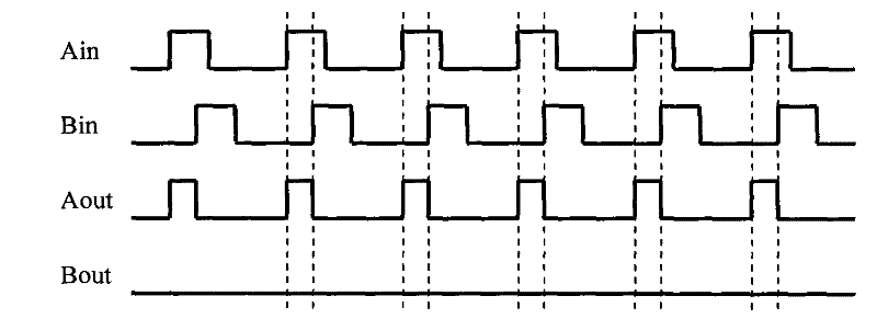
[0023] The present invention mainly includes three functional modules: a ±180° phase discrimination module 4 , a frequency divider 5 and a counting and averaging module 6 . The signal to be phase-detected is identified through the ±180°phase-detection module, and a phase square wave is generated. The pulse width of the phase square wave represents the magnitude of the signal phase difference. Several pulse widths are selected by the frequency divider to be counted by the counting and averaging module, and the counting average value of a single pulse width is obtained, and the phase difference can be accurately calculated from this value.

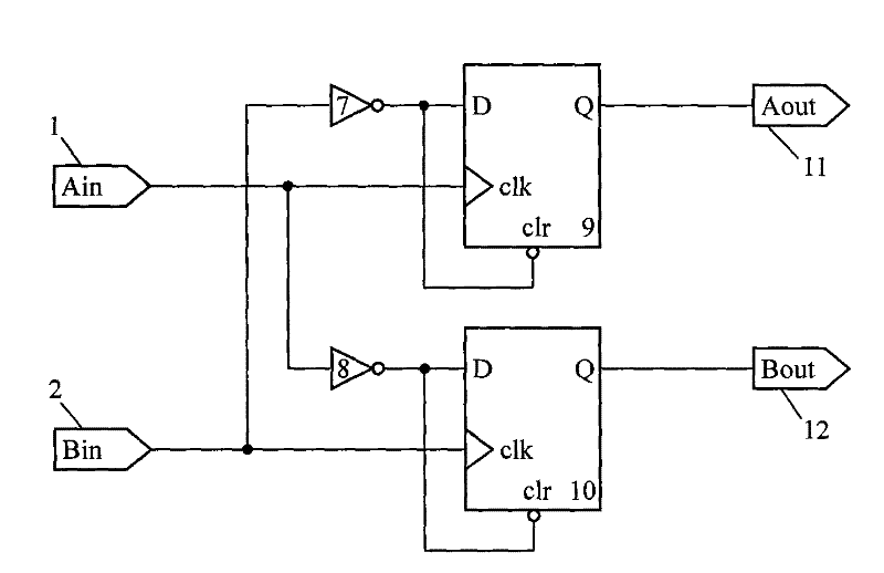
[0024] The ±180° phase detection module is mainly composed of two NOT gates and two D flip-flops, and the two output signals are used to realize signal direction discrimination.

[0025] The frequency divider divides the frequency of the input signal by M times, and selects M phase pulses in the phase square wave. The counting and averaging...


PUM


Abstract

The invention relates to a method and a device for detecting a signal phase difference, in particular to a high-precision + / -180 DEG digital phase distinguishing method based on a digital phase distinguishing principle and an applying device thereof. The high-precision + / -180 DEG digital phase distinguishing device which can distinguish the direction of a signal and reduce a random error comprises a + / -180 DEG phase distinguishing module, a frequency divider and a counting average module, wherein the + / -180 DEG phase distinguishing module is used for realizing signal direction distinguishing and generating a phase square wave; the frequency divider is used for dividing the frequency of the phase square wave, obtaining a plurality of pulse width signals and transmitting the pulse width signals to the counting average module; and the counting average module is used for respectively counting the pulse width signals selected by the frequency divider and solving a single pulse width counting average value. The invention is mainly used for the phase detection of signals of the measurement of a power factor in a power system, the measurement of a phase difference of a phase sensitive track circuit in a railway system, the wind speed measurement of an ultrasonic tunnel, phase difference measurement in a Coriolis mass flowmeter, and the like.

Description

technical field [0001] The present invention relates to a detection method for signal phase difference, more specifically, the present invention relates to a high-precision ±180° digital phase detection method based on the digital phase detection principle and its implementing device. technical background [0002] At present, phase detection technology has developed rapidly and is widely used in various measurement and control projects, such as the measurement of power factor in power systems, the measurement of phase difference of phase-sensitive track circuits in railway systems, the measurement of wind speed in ultrasonic tunnels, and the measurement of Coriolis mass flowmeters. Phase difference measurement and so on. Typical phase detection methods include: multiplication method, vector method, numerical sampling method, zero-crossing phase detection method, etc. Various phase identification methods have different application conditions, measurement ranges, measurement ...

Claims


Application Information

Patent Timeline
Patent Type & Authority Patents(China)
IPC IPC(8): H03D13/00
Inventor 段发阶欧阳涛李孟麟欧冰洁
Owner 善测(天津)科技有限公司
Learn More