
Underground rescue robot

An underground rescue and robot technology, applied in the field of robot and mechanical rescue, can solve the problems of time-consuming, labor-intensive and unacceptable, and achieve the effects of wide application range, avoiding damage and quick response

Inactive Publication Date: 2012-11-14
NORTHEASTERN UNIV LIAONING
View PDF0 Cites 0 Cited by
  • Summary
  • Abstract
  • Description
  • Claims
  • Application Information

AI Technical Summary

Problems solved by technology

[0005] Aiming at the problem that the existing downhole rescue methods are time-consuming and labor-intensive, sometimes not desirable, and most of the existing downhole rescue devices are temporarily self-made. Underground rescue robot for underground rescue tasks

Method used


Image

  • Underground rescue robot
  • Underground rescue robot
  • Underground rescue robot

Examples


Embodiment 1

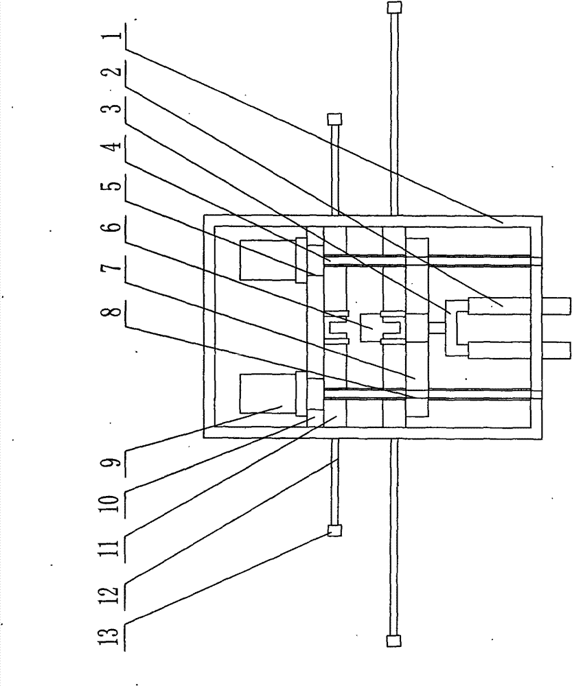
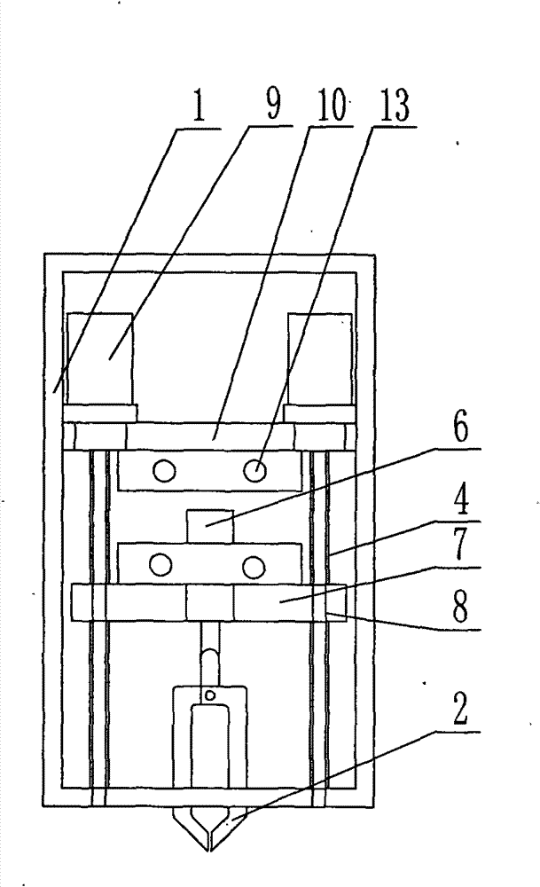
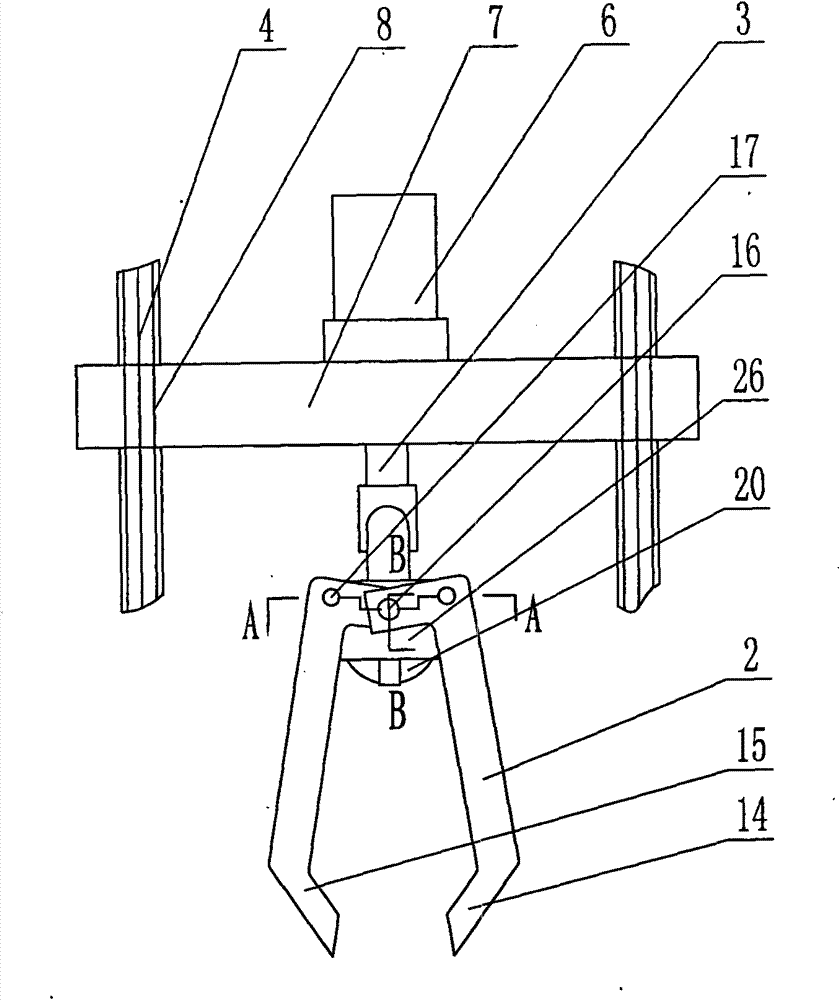
[0020] As shown in the figure, a kind of underground rescue robot comprises a frame 1, and a fixed platform 10 with a through hole 5 is fixed in the frame 1, and a lifting motor 9 is fixed above the fixed platform 10, and the motor shaft of the lifting motor 9 The through hole 5 of the fixed platform 10 is connected with the leading screw 4; the lifting platform 7 with thread 8 is arranged under the fixed platform 10, and the thread 8 of the lifting platform 7 corresponds to the leading screw 4; The bottom of the lifting platform 7 and the top of the lifting platform 7 are respectively provided with a hydraulic cylinder 11, and the piston rod of the hydraulic cylinder 11 is connected with the telescopic rod 12; The through hole 5 is connected with one end on one side of the three-terminal connector 3, and the two ends on the other side of the three-terminal connector 3 are respectively connected with the first fixed plate 26 and the second fixed plate 29 having a groove 25 and ...

Embodiment 2

[0022]As shown in the figure, a kind of underground rescue robot comprises a frame 1, and a fixed platform 10 with a through hole 5 is fixed in the frame 1, and a lifting motor 9 is fixed above the fixed platform 10, and the motor shaft of the lifting motor 9 The through hole 5 of the fixed platform 10 is connected with the leading screw 4; the lifting platform 7 with thread 8 is arranged under the fixed platform 10, and the thread 8 of the lifting platform 7 corresponds to the leading screw 4; The bottom of the lifting platform 7 and the top of the lifting platform 7 are respectively provided with a hydraulic cylinder 11, and the piston rod of the hydraulic cylinder 11 is connected with the telescopic rod 12; The through hole 5 is connected with one end on one side of the three-terminal connector 3, and the two ends on the other side of the three-terminal connector 3 are respectively connected with the first fixed plate 26 and the second fixed plate 29 having a groove 25 and t...


PUM


Abstract

The invention discloses an underground rescue robot, which belongs to the technical field of robots. The invention provides the underground rescue robot, which can perform underground rescue task with less labor, high speed, high accuracy and high efficiency. The robot comprises a machine frame, wherein a fixed table with a through hole is fixed in the machine frame, a lifting motor is fixed above the fixed table and the motor shaft of the lifting motor is connected with a screw rod through the through hole of the fixed table; a lifting table with threads is arranged under the fixed table, and the threads of the lifting table correspond to those of the screw rod; hydraulic cylinders are arranged under the fixed table and above the lifting table respectively; the piston rods of the hydraulic cylinders are connected with telescopic rods; a rotating motor is fixed above the lifting table; the motor shaft of the rotating motor is connected with one end on one side of a three-end connecting piece through a through hole on the lifting table; and the two ends on the other side of the three-end connecting piece are connected with the top ends of first and second fixed plates with grooves and through holes, and mechanical arms are arranged on the first fixed plate and the second fixed plate.

Description

Technical field: [0001] The invention belongs to the technical field of robots, and in particular relates to an underground rescue robot, which is mainly used in the field of mechanical rescue. Background technique: [0002] The existing underground rescue devices are immature, and generally rely on manpower to carry out the rescue. The specific rescue method is that the rescuer is turned upside down at the wellhead, and the person to be rescued is pulled up or pulled out with life-saving equipment such as a rope. Wellhead. This is time-consuming and labor-intensive, and the efficiency is low. The key is that this method is not necessarily desirable, and the success rate is small. [0003] At present, the few underground rescue devices adopted in the rescue process are all temporarily self-made by rescuers in emergency situations. For example, China Police Network once reported: On September 2, 2009, a peasant woman in Sangzhuang Village, Liyang Town, Junxian County, Henan...

Claims


Application Information

Patent Timeline
Patent Type & Authority Patents(China)
IPC IPC(8): A62B99/00B25J9/00
Inventor 沈岗师帅李振远邹康权杨翊王丹
Owner NORTHEASTERN UNIV LIAONING
Learn More