Automatic valve locking device and control method thereof

An automatic locking and gate technology, which is applied in water conservancy projects, sea area engineering, coastline protection, etc., can solve the problems affecting the passage capacity and operation safety of ship locks, the speed of gate movement cannot be controlled, and the positioning precision is low, so as to achieve accurate locking action , simple structure and low processing cost

Active Publication Date: 2010-05-12
杭州华辰电力控制工程有限公司
View PDF0 Cites 10 Cited by
  • Summary
  • Abstract
  • Description
  • Claims
  • Application Information

AI Technical Summary

Problems solved by technology

However, due to the limitation of the installation of the device and the conditions of the opening and closing equipment, in the actual application of the locking device, due to the inevitable low positioning accuracy and poor repeatability of the opening and closing equipment, the gate often deviates from the locking position and requires manual intervention, so that it needs to be locked. Repeated operations and other problems, for the gates that require frequent opening and closing, such as the lifting and horizontal navigable gates installed in the navigable ship lock, the contradictions caused by the above problems are more prominent, which will affect the passing capacity and operation safety of the ship lock. Improve this
[0003] In addition, the control method of the gate in the prior art operates at a constant speed during the rising and falling of the gate.
When the lifting gate is used, it cannot control the speed of the gate movement. Because there is no deceleration, when the gate hits the limit switch, the gate cannot stop in time but has a buffering process, and the gate will open too far, causing the gate to rush to the top is extremely dangerous
A slow speed is also required when the lifting door is unlocked during the descent process, and the fast operation of the conventional operation is also easy to cause the gate to rush to the top

Method used


Image

  • Automatic valve locking device and control method thereof
  • Automatic valve locking device and control method thereof
  • Automatic valve locking device and control method thereof

Examples


Embodiment Construction

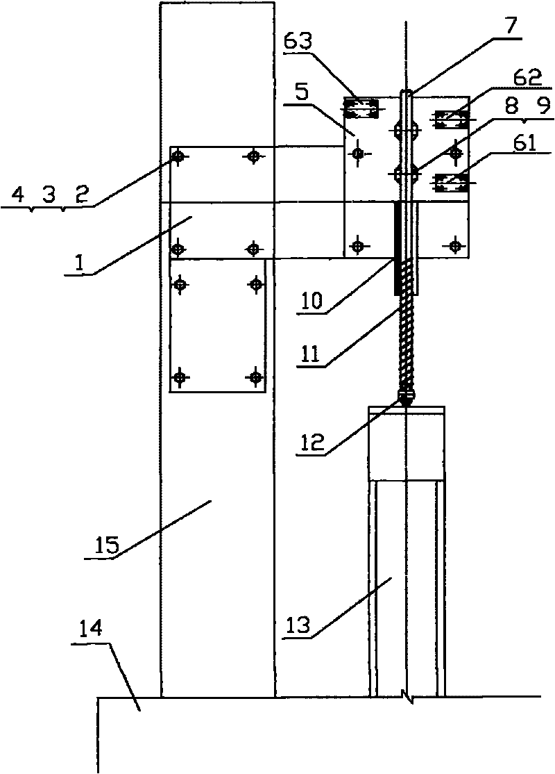
[0017] see figure 1 , the present invention installs one set on the left and right sides of the gate body, and each set includes a support plate 1, a mounting plate 5, a travel switch 6, a guide rod 7, an impact sleeve 8, a guide rod sleeve 10, a spring 11, and a locking support 13 and thin nuts 12, the support plate 1 is fixed on the wall 15 by welding nuts 2, bolts 3 and spring washers 4, and the mounting plate 5 is fixed on the support plate 1 by spring washers 4, bolts 3 and weld nuts 2 Above, the mounting plate 5 is provided with a guide rod cover 10, the guide rod cover 10 is provided with a guide rod 7, the lower end of the guide rod 7 is covered with a spring 11, and the lowermost end of the guide rod 7 is provided with a thin nut 12, which impacts The sleeve 8 is fixed on the guide rod 7 through the set screw 9. The impact sleeve 8 includes an upper impact sleeve 81 and a lower impact sleeve 82. Both the upper impact sleeve 81 and the lower impact sleeve 82 are instal...


PUM


Abstract

The invention discloses an automatic valve locking device and a control method thereof. The automatic valve locking devices are arranged on the left and right sides of a valve body respectively; each automatic valve locking device comprises a pedestal plate, a mounting plate, travel switches, a guide rod, an impact sleeve, a guide rod sleeve, a spring, a locked pedestal and a thin nut, wherein the pedestal plate is fixed on a wall body; the mounting plate is fixed with the pedestal plate and is provided with the guide rod sleeve; the guide rod is arranged in the guide rod sleeve; the lower end of the guide rod is sleeved with the spring, while a lowest end is provided with the thin nut; the guide rod is provided with the impact sleeve; the travel switches are arranged on the periphery of the impact sleeve on the mounting plate; and the locked pedestal is arranged under the guide rod and is fixed on the valve body. In the control method, a control system consisting of a programmable logic controller PLC, a frequency converter and an opening meter is adopted for control over the automatic valve locking device in a way of continuously closed-loop operation at a given speed. The device of the invention is high in stop accuracy and good in repeatability; and the control method is reliable in locking.

Description

technical field [0001] The invention relates to an automatic locking device and a control method for the fully open position or the set open position of a lifting plane gate, a rising and horizontal plane gate, an arc gate, etc. Locking, the application of the present invention can realize accurate and reliable fully automatic control on occasions requiring frequent locking and unlocking. Background technique [0002] All kinds of gates of hydropower and water conservancy projects and navigable buildings generally need to be kept in the fully open state through locking devices after they are operated to the fully open position, so as to realize the functions of safe discharge of the orifice and ship navigation. Existing locking device mainly adopts two kinds of mechanical type and hydraulic control type. Mechanical locking devices are widely used, and the most common type is the "hanging and detachable" lock consisting of a card body, a support shaft and a locking base. Its...

Claims


Application Information

Patent Timeline
Patent Type & Authority Applications(China)
IPC IPC(8): E02B7/26
Inventor 马时浩刘勇张晋涛吴元军汪云祥姚震雷
Owner 杭州华辰电力控制工程有限公司
Why Eureka
Try Eureka