
Digital storage oscilloscope with function of time base fine tuning

A digital storage and oscilloscope technology, applied in the direction of digital variable display, etc., can solve the problems of impossible time base fine-tuning function, low flexibility, limited number of frequency division modules, etc.

Inactive Publication Date: 2010-05-12
UNIV OF ELECTRONICS SCI & TECH OF CHINA
View PDF0 Cites 18 Cited by
  • Summary
  • Abstract
  • Description
  • Claims
  • Application Information

AI Technical Summary

Problems solved by technology

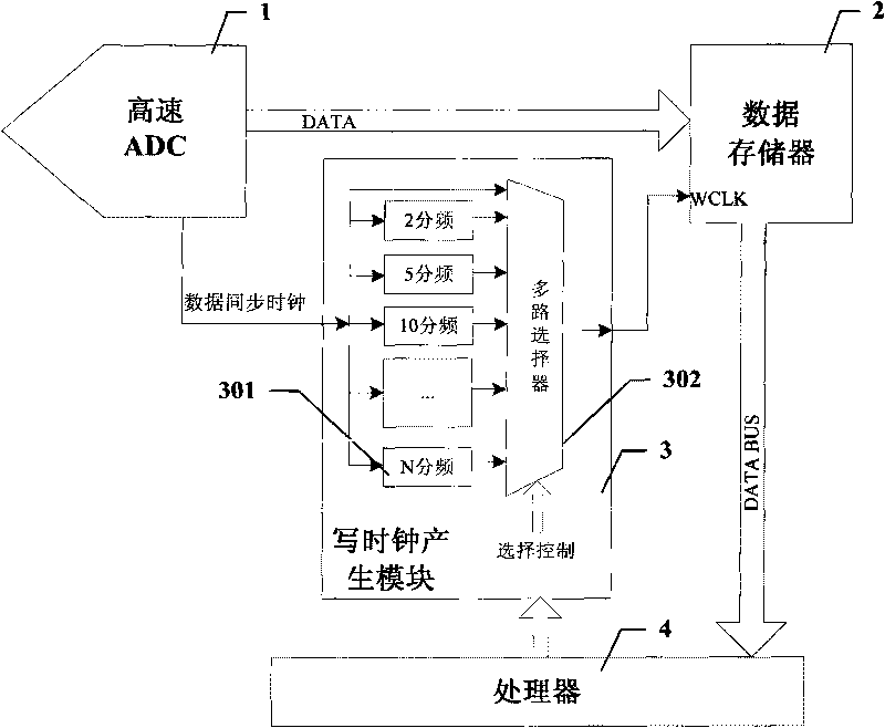
[0019] The above-mentioned method of realizing variable sampling rate by frequency division of data synchronization clock needs to set a frequency division correspondingly under each time base gear, and its flexibility is not high, especially in a system with a lot of time base gears. The number of frequency division modules required is large
Although this method is feasible to realize 1-2-5 stepping time base gears, under the time base fine-tuning, due to the required time base gears are more and denser, the number of frequency division modules is limited after all, it is impossible to realize Time base fine-tuning function

Method used


Image

  • Digital storage oscilloscope with function of time base fine tuning
  • Digital storage oscilloscope with function of time base fine tuning
  • Digital storage oscilloscope with function of time base fine tuning

Examples


Embodiment 1

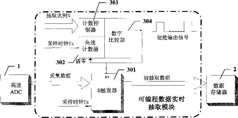
[0039] image 3 yes figure 2 A functional block diagram of a specific implementation of the shown programmable data real-time extraction module.

[0040] Such as image 3 As shown, in this embodiment, the programmable data stream real-time extraction module 3 is designed based on the principle of a counting comparator.

[0041] In this embodiment, the programmable data stream real-time extraction module 3 includes a D flip-flop 301, a high-speed counter 302, a counting controller 303, and a digital comparator 304;

[0042] The D flip-flop 301 receives the collected data from the high-speed ADC 1, and when its enable terminal EN is at a high level, it latches the input sampled data, and sends the latched sampled data to the data memory 2 at the next sampling clock fs storage in

[0043]In this embodiment, the extraction ratio control word is the extraction ratio N value, which is set by the processor 4, wherein N=1, 2, 3, ..., and stored in the counting controller 302; the...

Embodiment 2

[0056] Figure 4 yes figure 2 It is a functional block diagram of another specific implementation of the programmable data real-time extraction module shown.

[0057] Such as Figure 4 As shown, in this embodiment, the programmable data stream real-time extraction module 3 is designed based on the accumulator principle.

[0058] In this embodiment, the programmable data stream real-time extraction module 3 includes a D flip-flop 301, a high-speed accumulator 305, and an enable pulse generation module 306;

[0059] The D flip-flop 301 receives the collected data from the high-speed ADC 1, and when its write enable terminal is at a high level, it latches the input sampled data, and sends the latched sampled data to the data memory 2 at the next sampling clock fs storage in

[0060] Processor 4 generates the corresponding extraction ratio control word K according to the extraction ratio N value corresponding to the current time base gear, and sends it into the high-speed acc...


PUM


Abstract

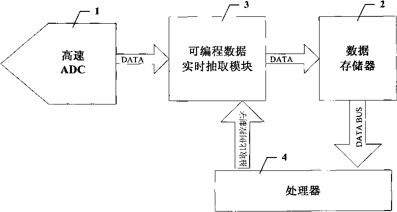
The invention discloses a digital storage oscilloscope with a function of time base fine tuning, which comprises a high-speed ADC, a data storage device, a processor and a programmable data real-time extraction module, wherein the high-speed ADC outputs acquisition data to the programmable data real-time extraction module to perform real-time extraction, and the extraction proportion is set according to extraction proportion control words from the processor; the acquisition data after the real-time extraction is sent into the data storage device for storage; and the extraction proportion control words are determined by the fine tuning of time base shifts as required. The digital storage oscilloscope adopts a method for performing the real-time extraction on the acquisition data by using the programmable data real-time extraction module so as to change the sampling rate of an acquisition system. In the digital storage oscilloscope, the extraction proportion can be changed by only changing the extraction proportion control words of the programmable data real-time extraction module by the processor, more and more intensive sampling rates can be generated, and particularly slow time base shifts can be generated, so the function of the time base fine tuning of the digital storage oscilloscope is achieved.

Description

technical field [0001] The invention relates to the technical field of digital storage oscilloscopes, in particular to a digital storage oscilloscope with a time base fine-tuning function. Background technique [0002] In the oscilloscope, both the vertical sensitivity and the time base are divided into several files in the way of 1-2-5 sequence steps. In actual use, if only the above-mentioned methods are used to observe the waveform, in many cases it will bring certain restrictions to the observation. A very likely situation is that when the waveform is displayed on the oscilloscope, the waveform cannot be displayed with the best effect. As far as the vertical sensitivity is concerned, either the amplitude of the observed waveform is too large and exceeds the screen display, or the amplitude is too small and does not meet the integer grid, which brings certain difficulties to the measurement of the amplitude of the waveform; as far as the time base is concerned, either th...

Claims


Application Information

Patent Timeline
Patent Type & Authority Applications(China)
IPC IPC(8): G01R13/02
Inventor 田书林叶芃邱渡裕张沁川曾浩
Owner UNIV OF ELECTRONICS SCI & TECH OF CHINA
Learn More