[0006] The purpose of the present invention is to provide a kind of PEA space charge testing device that can measure the
conduction current in order to solve the problem that the
conduction current and the space charge can not be connected at present described in the background technology, and it is characterized in that the
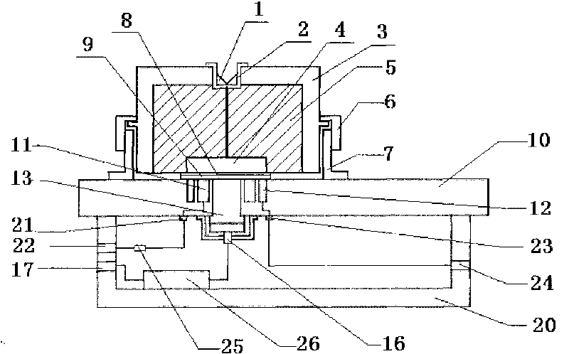
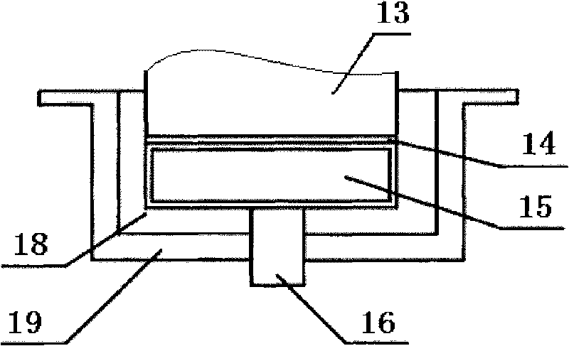
measurement device is mainly composed of It consists of five parts, namely the upper electrode, the lower electrode, the space charge collection channel, the current signal collection channel and the pulse input channel. The lower electrode separator 10 is a rectangular insulating plate, and the truncated conical lower electrode central column 13 is fixed on the lower electrode from bottom to top. In the circular hole in the middle of the electrode separator 10, the lower electrode inner ring 11 and the lower electrode outer ring 12 are coaxially embedded in the lower electrode separator 10 with the lower electrode central column 13, the lower electrode central column 13, the lower electrode inner ring 11 and the lower electrode central column 13. The upper end surface of the electrode outer ring 12 and the upper surface of the lower electrode separator 10 form the lower electrode plane in the same plane, the
piezoelectric sensor 14 is placed under the lower end surface of the lower electrode center column 13, and the
organic glass column 15 coated with
metal film is placed Under the
piezoelectric sensor 14, the lower electrode central column insulating sleeve 18 covers the bottom of the lower electrode central column 13, the
piezoelectric sensor 14 and the plexiglass column 15 coated with
metal film are placed in the metal shell 19 of the space charge collector, and the space charge The metal casing 19 of the collector is fixedly connected to the lower surface of the lower electrode separator 10, and the piezoelectric sensor 14, the
organic glass column 15 coated with metal film, the insulating sleeve 18 of the lower electrode central column and the lower end surface of the lower electrode central column 13 are pressed tightly, and the rectangular parallelepiped The lower electrode metal shell 20 is fixedly connected to the lower surface of the lower electrode separator 10, and the charge signal SMA coaxial socket 16 is fixedly connected in the center hole of the metal shell 19 of the space charge collector, and the inner conductor of the charge signal SMA coaxial socket 16 passes through The insulating sleeve 18 of the center column of the lower electrode is in reliable electrical contact with the
gold film on the lower surface of the metal-coated plexiglass column 15, and the charge signal
preamplifier 26 is placed in the metal shell 20 of the lower electrode, and the input terminal of the charge signal
preamplifier 26 is connected to the charge signal
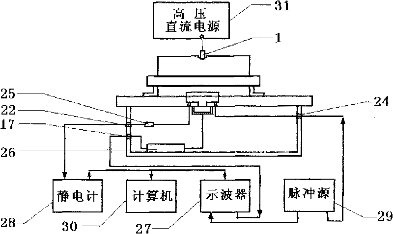
preamplifier. The signal SMA coaxial socket 16 is connected, the output end is connected to the charge signal SMA coaxial plug 17 fixed on the left side wall of the lower electrode metal shell 20, and the current signal SMA coaxial curved socket 21 is fixed on the lower surface of the lower electrode separator 10, The inner conductor of the current signal SMA coaxial curved socket 21 is connected to the inner ring electrode 11 of the lower electrode, one end of the
current limiting resistor 25 placed in the lower electrode metal shell 20 is connected to the inner conductor of the current signal SMA coaxial curved socket 21, and the other end It is connected with the current signal SMA coaxial plug 22 fixed on the left side wall of the lower electrode metal shell 20, the pulse input SMA coaxial curved socket 23 is fixed on the lower surface of the lower electrode separator 10, and the inner surface of the pulse input SMA coaxial curved socket 23 The conductor is connected to the outer ring electrode 12 of the lower electrode, and the pulse input SMA coaxial plug 24 is fixedly connected to the right side wall of the lower electrode metal shell 20 and connected to the pulse input SMA coaxial bent socket 23 with bare wires;

