
On-line monitoring system for direct-current power supply and storage battery

A monitoring system and DC power supply technology, applied in the field of detection, can solve problems such as low work efficiency, inability to know immediately, and high security risks, and achieve the effects of improving safety and reliability, realizing modern management, and ensuring safe operation.

Active Publication Date: 2010-05-12
PLUKE TECH
View PDF0 Cites 53 Cited by
  • Summary
  • Abstract
  • Description
  • Claims
  • Application Information

AI Technical Summary

Problems solved by technology

[0004] 1. Defects of manual inspection method: (1) Big safety risk
Due to complex site conditions, small space, high voltage, and the presence of flammable and corrosive gases, there is a greater risk when the staff go to the site for inspection
(2) Time-consuming and labor-intensive, high cost, and low work efficiency; (3) It is impossible to grasp the status of on-site equipment anytime and anywhere, and when there is a safety hazard, it cannot be known immediately, which often leads to major accidents, resulting in major economic and human losses
(4) It is impossible to realize the trend prediction of equipment status
(5) When the amount of data is large, data management and various reports and query statistics are more difficult
[0005] 2. Failure to understand the problem from a systematic point of view
Defects of single detection and monitoring methods only for batteries: batteries are complex electrochemical products, in order to ensure their normal use and prolong their life, careful management and maintenance are required
Many batteries are not worn out, but charged. The fundamental reason is that the characteristics of the charger are poor, especially the indicators such as voltage stabilization accuracy, current stabilization accuracy, and ripple voltage coefficient are poor, resulting in early damage to the battery.

Method used


Image

  • On-line monitoring system for direct-current power supply and storage battery
  • On-line monitoring system for direct-current power supply and storage battery
  • On-line monitoring system for direct-current power supply and storage battery

Examples


Embodiment Construction

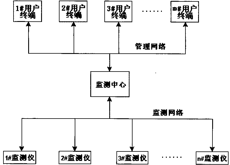
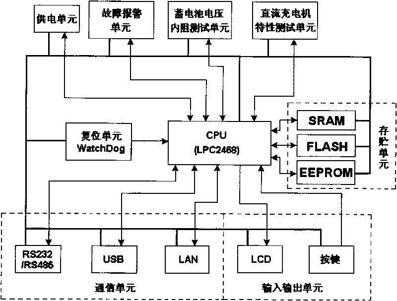
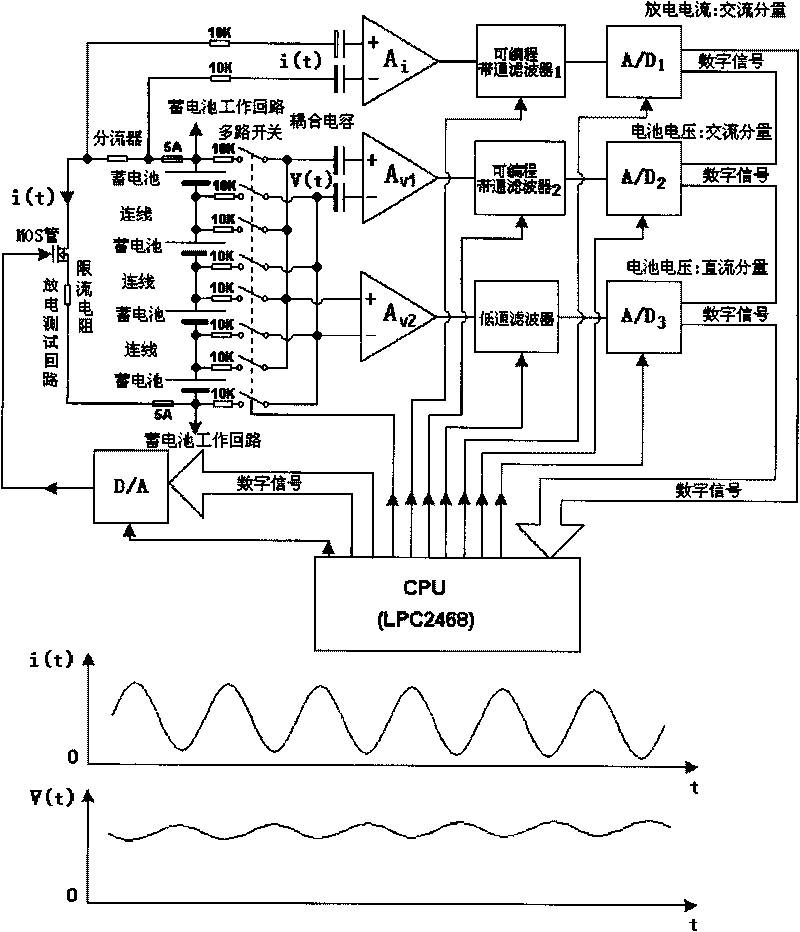
[0032] Such as Figure 1~5 A DC power supply and storage battery online monitoring system of the present invention is shown. The system is composed of an online monitoring instrument, a monitoring center, a user terminal, a management network and a monitoring network. The online monitoring instrument is composed of a CPU, a battery voltage internal resistance test Unit, DC charger characteristic test unit, power supply unit, communication unit, input and output unit, fault alarm unit, reset unit, and storage unit, to realize on-line monitoring of on-site batteries and DC chargers and pass the monitoring data through the monitoring Network transmission to the monitoring center. The monitoring center is a large server running database application management software, receiving the monitoring data from the online monitor, and storing and managing the monitoring data in the form of a large database; Respond to various commands sent by the user terminal via the management network, ...


PUM


Abstract

The invention discloses an on-line monitoring system for a direct-current power supply and a storage battery, which comprises an on-line monitor, a monitoring centre, a user terminal, a monitoring network and a management network, wherein the on-line monitor consists of a CPU, a storage battery voltage and internal resistance test unit, a direct-current charger characteristic test unit, a power supply unit, a communication unit, an input-output unit, a fault alarm unit, a reset unit and a storage unity, monitors a field storage battery and the direct-current charger online and transmits monitoring data to the monitoring centre through the monitoring network; the monitoring centre is a large-scale server, which receives the monitoring data transmitted from the on-line monitor and performs storage management on the monitoring data in a large-scale database mode; the system responses various commands of the user terminal, and receives the commands of the user terminal to perform various controls on the on-line monitor installed on-site.

Description

technical field [0001] The invention relates to an on-line monitoring system for a DC power supply and a storage battery, belonging to the technical field of detection. Background technique [0002] As an important part of the power system, the backup power system composed of batteries and DC chargers plays a key role in storing electric energy, coping with power grid abnormalities and special working conditions, and maintaining the normal operation of the system. It is the last line in the field of high reliability power guarantee. line of defense. The system is widely used in electric power, communications, government agencies, finance, securities, insurance, radio and television, transportation, manufacturing, military, education, scientific research, public facilities and other industries. The stability of the backup power system and the actual capacity that can be provided to the load during the discharge process are of great significance to ensure the safe operation o...

Claims


Application Information

Patent Timeline
IPC IPC(8): G01R31/40G01R31/36
Inventor 王汝钢
Owner PLUKE TECH
Learn More