Method for electrically forecasting danger in underground tunneling engineering

A technology of advanced forecasting and hidden dangers, applied in earth drilling, re-radiation, geophysical measurement, etc., can solve the problems of difficult instrument processing, inconvenient construction coordination, expensive instruments and equipment, etc., to achieve convenient construction coordination, early warning and forecasting The effect of low cost and simple electrode arrangement

Inactive Publication Date: 2010-05-12
CENT SOUTH UNIV
0 Cites 38 Cited by

AI-Extracted Technical Summary

Problems solved by technology

At present, the electrical prospecting used for hidden danger prediction is carried out in the roadway. Due to the influence of space constraints and electric field interference factors, it is difficult to obtain data with high signal-to-noise ratio for early warning and forecasting of hidden dangers; the BEAM method used abroad for electrical prospecting , the instruments and equipment are expensive and require special software, which are rarely imported in China and are inconvenient to promote; in addition, due to the need for power supply in...

Abstract

The invention discloses a method for electrically forecasting a danger in underground tunneling engineering, which comprises: building an approximately even current field in the direction of a tunnel or a laneway by burying long-distance fixed-source first and second power supply electrodes underground in the direction of the tunnel and the laneway; measuring and recording current field change under the background of the approximately even current field by using a measuring electrode buried in tunnel heading face of the laneway and a measuring electrode arranged in or outside the tunnel; and predicating and forecasting a danger around the tunnel heading face according to a law for the change of the electric field. The method has the advantages that: an electrical instrument can be placed in ground station for observation; intra-laneway power supply is avoided; the arrangement of the electrodes is convenient; and the early warning and forecasting cost is low. The method can be widely used in the field of projections involving laneway or tunnel construction, such as coal mine, mine production, communication, water conservancy and hydropower and subway projections.

Application Domain

Technology Topic

Image

  • Method for electrically forecasting danger in underground tunneling engineering
  • Method for electrically forecasting danger in underground tunneling engineering
  • Method for electrically forecasting danger in underground tunneling engineering

Examples

  • Experimental program(1)

Example Embodiment

[0022] The present invention will be further described below with reference to the drawings and specific embodiments.
[0023] Fundamental:
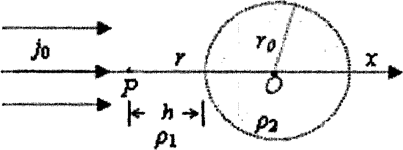
[0024] In electrical exploration, when the first power supply electrode and the second power supply electrode are grounded for power supply, the electric field changes very little in the 1/3 or 1/2 section between the first power supply electrode and the second power supply electrode, which can be approximately regarded as uniform Electric field; the common approximate equiaxed geological hazards in nature, such as underground caves, goaf cavities or sac-shaped hazards, can be approximated as spheres.
[0025] Assuming that the rock mass in a homogeneous and isotropic half-space (resistivity ρ 1 In ), the underground hidden danger in front of the face 6 is a spherical structure with a dielectric resistivity of ρ 2. When the filling medium is water or mud, ρ 2 2 , Is a low resistance abnormal body, when the filling medium is air, ρ 2ρ 1 , Is a high resistance abnormal body. See the principle figure 1.
[0026] Assuming that the potential of the spherical center is zero, the potential of any point P in the underground medium that points to the center of the sphere along the direction of the current field can be calculated:
[0027] U = [ 1 + 2 ρ 2 - ρ 1 2 ρ 2 + ρ 1 ( r 0 r ) 3 ] j 0 ρ 1 r - - - ( 1 )
[0028] Where r 0 Is the radius of the hidden danger of the sphere, r is the distance from the observation point to the center of the sphere, h is the distance from point P to the surface of the sphere, j 0 Is the current density of the uniform current field, and the direction is the tunnel direction x. The first term in the formula is the background potential when the sphere exists, and the second term is the abnormal potential.
[0029] If the electric field intensity is taken as the observation signal, its expression is:
[0030] E = j 0 ρ 1 - 4 ρ 2 - ρ 1 2 ρ 2 + ρ 1 ( r 0 r ) 3 j 0 ρ 1 - - - ( 2 )
[0031] The percentage of abnormal electric field intensity can be calculated:
[0032] P E = 4 X | ρ 2 - ρ 1 2 ρ 2 + ρ 1 ( r 0 r ) 2 | X 100 % - - - ( 3 )
[0033] For any point in underground space, there is a relationship between electric field strength and apparent resistivity in electrical exploration:
[0034] ρ s =E/j 0 (4)
[0035] Therefore, the measured data of the electric field intensity can be converted into the result of the apparent resistivity, and the abnormal change rate of the electric field intensity can also be equivalent to the abnormal change rate of the apparent resistivity.
[0036] According to expression (3), the ideal resolving power during electric field intensity measurement can be calculated. As shown in Table 1, the limit resolving power is calculated with 10% as the effective abnormality, and the characterizing parameter of the limit resolving power is h/r 0. It can be seen from Table 1 that the electrical prospecting method mentioned in the present invention has a good resolution capability for the abnormal spherical structure.
[0037] Table 1. Limit resolution ability when the forward current field approaches the hidden danger of the sphere from the radial direction in the underground uniform half space
[0038]
[0039] If the hidden danger is a low-resistance or high-resistance cylindrical anomaly, the resolution capability of electrical exploration can be improved for anomalous objects with the same radius perpendicular to the direction of the roadway strike; for hidden troubles such as faults, after calculation, Electrical exploration also has a good resolution ability; for the discussion of the principle of electrical exploration with induced polarization method, you can refer to related materials, so I won’t go into details here.
[0040] The above theories provide theoretical support for the advanced prediction of hidden dangers.
[0041] Example 1:
[0042] For the hidden danger of water storage, for example, the radius of the hidden danger of the sphere is 5 meters, the resistivity of the filled water is 50 ohm meters, the resistivity of the surrounding rock is 1000 ohm meters, and the current density is 0.1 mA/m. 2 , R takes 6 to 100 meters, as shown in the figure on the abscissa. Calculate the electric potential and electric field intensity of the observation point P according to formula 1 and formula 3.
[0043] From figure 2 It can be seen that for the above-mentioned simulated hidden dangers, when the tunnel face moves forward from 100 meters to 20 meters close to the low-resistance hidden danger body, the potential decreases from 500mV to 100mV; image 3 It can be seen that when the tunnel face is approaching a hidden danger, as shown in the figure, the electric field intensity decreases sharply from 40 meters to 6 meters.
[0044] Example 2:
[0045] For spherical hidden hazards such as unfilled caves, the hidden hazard radius of the sphere is 5 meters, the resistivity of the hollow sphere is infinite (∞), the resistivity of the surrounding rock is 1000 ohm·m, and the current density is 0.1 mA/m 2 , R takes 6 to 100 meters, which is image 3 The abscissa shown in. Calculate the theoretical potential and electric field strength of the observation point P according to formula 1 and formula 3.
[0046] From Figure 4 It can be seen that for the above-mentioned simulated hidden dangers, when the tunnel face moves forward from 100 meters to 20 meters close to the high-impedance hidden danger body, the potential is reduced from 10V to 2V; Figure 5 It can also be seen that when the face is approaching hidden dangers, such as Figure 5 The electric field intensity decreases sharply from 40 meters to 6 meters.
[0047] It is worth noting that from the electric field intensity distribution characteristics of the two calculation examples, it can be seen that when the tunnel face is approaching a hidden danger, the electric field intensity changes sharply, which is a good early warning parameter or sign.
[0048] Measurement method 1: see Image 6 , Prepare electrical equipment 11 such as a set of electric field measuring equipment or induced polarization measuring equipment for electrical exploration, a laptop computer 2, and the power supply 9 is connected to the electrical equipment 11 through the synchronization cable 10, and the electrical equipment 11 passes The communication line 17 is connected to the notebook computer 2, and these devices are all arranged on the ground 15. According to the design of the entrance and exit position and direction of the tunnel or roadway, the first power supply electrode 12, the second power supply electrode 13, the first power supply electrode 12 and the second power supply electrode 12 are arranged on the extension line 14 of the roadway section to be tested in the direction of the ground surface 15 The second power supply electrode 13 is buried near the surface 15 or buried in a well through a borehole. The distance between the first power supply electrode 12 and the second power supply electrode 13 is greater than or equal to twice the predicted distance. If the buried depth of the roadway is large, the distance between the power supply electrodes will be increased Or electrode depth, the settings of the first power supply electrode 12 and the second power supply electrode 13 are arranged in sections according to the roadway excavation progress. The first power supply electrode 12 and the second power supply electrode 13 are respectively connected to the positive and negative poles of the power supply 9 of the electrical method instrument through a wire 1; the front end of the excavated roadway 5 is the roadway 8 to be excavated, and the back end of the excavated roadway 5 is connected to the roadway shaft 4 , The first measuring electrode 7 is embedded in the tunnel face 6 as the positive electrode of the measuring electrode. This point is also the recording point of the potential measurement. Set the coordinate to x; the second measuring electrode and the second power supply electrode 13 (negative) of the power supply electrode The wire is connected; the external power supply is connected to the electric method instrument 11. Turn on the electrical method instrument 11, the measured data potential difference ΔU of the electrical method instrument 11 M (x) or polarizability a(x) is output through the port or read to the computer 2 to store and draw ΔU MN The (x)-x curve or a(x)-x curve shows that the electric field strength can be approximated by the potential difference between two adjacent observation points. Compared with the normal background electric field, the sudden change of the electric field strength or the polarizability characterizes the face 6 There are hidden dangers nearby or in front; the computer 2 uses its built-in speaker 3 or multi-level color warning as an alarm device, and can also notify the tunnel construction site through other communication methods.
[0049] Measurement method 2: Prepare a set of electric field measurement instruments or induced polarization measurement instruments for electrical exploration and a laptop computer. According to the design of the entrance and exit position and direction of the tunnel or roadway, the first power supply electrode 12, the second power supply electrode 13, and the first power supply electrode 12, the second power supply electrode 13 are arranged on the extension line of the roadway section to be tested on the direction of the ground surface 15 The distance of the power supply electrode 13 is greater than twice the distance of the predicted section, and the increase of the buried depth of the tunnel will increase the electrode distance or electrode depth; the first power supply electrode 12 and the second power supply electrode 13 are respectively connected to the positive and Negative; the first measuring electrode 7 and the second measuring electrode are placed on the same side of the tunnel, and the pole distance between the first measuring electrode 7 and the second measuring electrode is kept unchanged and arranged along the direction of the tunnel in subsequent measurements, and the electric field is measured The recording point is located at the midpoint of the first measuring electrode 7 and the second measuring electrode, and its coordinates are set to x. The first measuring electrode 7 and the second measuring electrode are respectively connected to the input terminal of the electrical exploration instrument through the wire 1; turn on the electrical instrument 11. Measurement data ΔU of electrical method instrument 11 MN (x) or polarizability a(x) output through the port or reading to computer storage to draw ΔU MN The (x)-x curve or a(x)-x curve shows that, compared with the normal background electric field, the sudden change of the electric field or the polarization rate indicates that there is a hidden danger near or in front of the face 6; the computer 2 uses its built-in speaker 3 or more Class-level color early warning is used as an alarm device, and it can also notify the tunnel construction site through other communication methods.

PUM

no PUM

Description & Claims & Application Information

We can also present the details of the Description, Claims and Application information to help users get a comprehensive understanding of the technical details of the patent, such as background art, summary of invention, brief description of drawings, description of embodiments, and other original content. On the other hand, users can also determine the specific scope of protection of the technology through the list of claims; as well as understand the changes in the life cycle of the technology with the presentation of the patent timeline. Login to view more.

Similar technology patents

Power grid region weather forecasting method based on dynamic downscaling

PendingCN113313290AHigh forecast accuracyImprove the forecast effectForecastingICT adaptationPower gridAtmospheric sciences
Owner:STATE GRID HENAN ELECTRIC POWER ELECTRIC POWER SCI RES INST +2

Rainfall forecasting and early warning system for complex terrain basin

PendingCN112070286AImprove accuracyHigh forecast accuracyForecastingComplex mathematical operationsNowcastingSoil wetness
Owner:GUIZHOU QIANYUAN POWER CO LTD +1

Classification and recommendation of technical efficacy words

  • High forecast accuracy
  • Safe to use

Rainfall forecasting and early warning system for complex terrain basin

PendingCN112070286AImprove accuracyHigh forecast accuracyForecastingComplex mathematical operationsNowcastingSoil wetness
Owner:GUIZHOU QIANYUAN POWER CO LTD +1

Power grid region weather forecasting method based on dynamic downscaling

PendingCN113313290AHigh forecast accuracyImprove the forecast effectForecastingICT adaptationPower gridAtmospheric sciences
Owner:STATE GRID HENAN ELECTRIC POWER ELECTRIC POWER SCI RES INST +2

Stretchable nonwoven fabric and tape

ActiveUS20100035500A1High stretchabilitySafe to useAdhesive dressingsFibre disintegrationThermal shrinkageNonwoven fabric
Owner:KURARAY CO LTD

Endoscope light source device

InactiveUS20090203966A1Safe to useSufficient qualitySurgeryEndoscopesLight sourceEndoscope
Owner:FUJIFILM CORP
Why Eureka
Try Eureka