
Rotor coil binding machine of wind power generator

A wind power generator and rotor coil technology, applied in the direction of wind power generation, manufacturing motor generators, electrical components, etc., can solve the problems of high labor intensity, unsuitable quality control, low efficiency, etc., achieve good results, ensure coil insulation structure, The effect of guaranteeing the mechanical properties

Inactive Publication Date: 2010-05-12
CRRC YONGJI ELECTRIC CO LTD
View PDF0 Cites 14 Cited by
  • Summary
  • Abstract
  • Description
  • Claims
  • Application Information

AI Technical Summary

Problems solved by technology

[0004] In order to solve the problem that the existing wind power generator rotor coil insulation relies on manual wrapping, there are problems of high labor intensity, low efficiency, and unsuitable quality control, and provides a wind power generator rotor coil wrapping with reasonable structure, good effect and better cost performance machine

Method used


Image

  • Rotor coil binding machine of wind power generator
  • Rotor coil binding machine of wind power generator
  • Rotor coil binding machine of wind power generator

Examples


Embodiment Construction

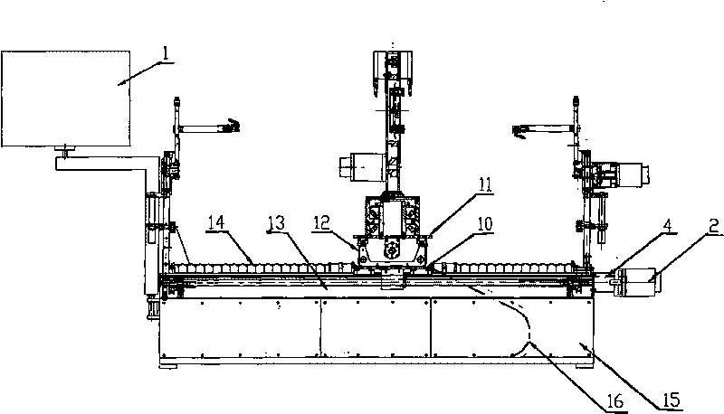
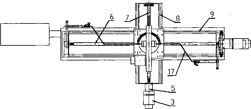
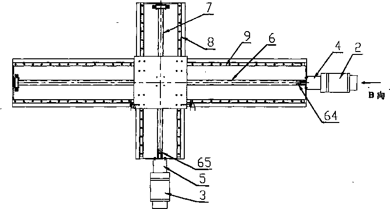
[0042] Wind power generator rotor coil wrapping machine includes numerical control system 1, machine base 15, feed system fixed on machine base 15, rotor coil clamping synchronization device and wrapping head fixed on feed system;

[0043] The feed system consists of an X-direction feed device and a Y-direction feed device; the X-direction feed device includes an X-direction grooved bed 13, and an X-direction ball screw 6 is supported inside the X-direction grooved bed 13, and the X-direction One end of the ball screw 6 is connected to the servo motor 2 through the coupling 64 and the reducer 4, and the top of the two ends of the X-direction grooved bed 13 is fixed with a linear guide rail 9, and a slider is installed on it, and an X-direction guide rail is fixed on the slider. Carrier 10, the bottom of the X-direction carriage 10 is fixed with a nut that matches the X-direction ball screw 6; the Y-direction feed device includes a Y-direction groove-shaped Bed 12, Y-direction ...


PUM


Abstract

The invention relates to the technology of rotor coil binding of generators, in particular to a rotor coil binding machine of a wind power generator. The invention solves the problems of large labor intensity, low efficiency and difficult control of quality caused by manual binding because of the insulation of the rotor coil of the traditional wind power generator. The rotor coil binding machine of the wind power generator comprises a numerical control system, a stand, a feeding system, a rotor coil clamping synchronous device and a lapping head, and mainly comprises a servo motor, a decelerator, a ball screw, as well as a trailing plate and a linear guide rail connected by a shaft coupler, a synchronous driving pulley, a synchronous driven pulley and a synchronous belt, wherein the synchronous belt with a tension wheel is arranged on the synchronous driven pulley, the shaft coupler is arranged between synchronous transmission pulleys at the bottom end, and the synchronous driving pulley and the synchronous driven pulley at the upper end are respectively provided with a rocking arm, a left clamp rod, a right clamp rod and a clamp. Compared with the binding machine in the prior art, the rotor coil binding machine of the wind power generator has reasonable structure, favorable effect and optimal cost performance.

Description

technical field [0001] The invention relates to a wrapping machine, in particular to a wrapping technique for a rotor coil of a generator, in particular to a wrapping machine for a rotor coil of a wind power generator. Background technique [0002] Wind energy is a renewable, non-polluting natural energy source, and a wind turbine is a power machine that converts wind energy into mechanical work. The cross-sectional size range of various types of rotor coils for wind turbines is roughly between 5×32 and 7×35 mm, and the forming length is between 1200 and 1600 mm, and is formed by bending copper bars. The middle of the rotor coil is a straight section, with flat bends, vertical bends, corners and nose shapes at both ends (see attached Figure 10-13 shown). The rotor coil is bent flat into a spiral shape, and the vertical bend is arc-shaped, with opposite corner directions and different nose angles. The rotor coil requires insulation 1 / 2, 1 / 3, 2 / 3 standard stacking, and the m...

Claims


Application Information

Patent Timeline
IPC IPC(8): H02K15/04
CPCY02E10/725Y02E10/72
Inventor 张帆郭风歧戈立娜
Owner CRRC YONGJI ELECTRIC CO LTD
Learn More