High-precision workbench and processing method thereof

A workbench and high-precision technology, which is applied in the direction of metal processing equipment, metal processing machinery parts, manufacturing tools, etc., can solve the problems of unsuitable control of precision, high production cost, and heavy labor, and achieve the solution of mechanical vibration, low cost, good reliability

Active Publication Date: 2010-05-19
齐重数控装备股份有限公司
View PDF0 Cites 4 Cited by
  • Summary
  • Abstract
  • Description
  • Claims
  • Application Information

AI Technical Summary

Problems solved by technology

These processes not only have a long cycle and unsuitable precision control, but also require a lot of labor and the production cost will naturally be quite high.

Method used


Image

  • High-precision workbench and processing method thereof
  • High-precision workbench and processing method thereof

Examples


example 1

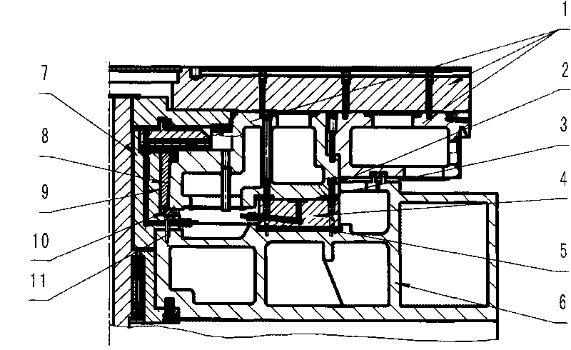
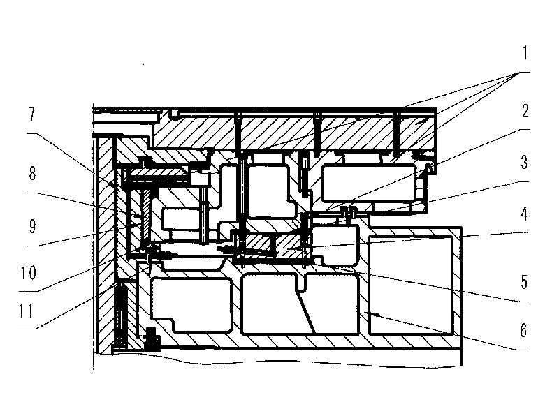
[0020] see figure 1 , The main shaft hydrostatic oil film 9 is set between the hydrostatic bearing bush 8 on the workbench 1 and the main shaft 7, this part is the key to ensure the radial runout accuracy of the workbench. The static pressure oil film 3 of the guide rail ring of the worktable is set between the worktable 1 and the guide rail ring 4, and this part is the key to ensure the runout accuracy of the end surface of the worktable. Between the guide rail ring 4 and the workbench base 6 is a high-precision guide rail positioning glue 5 , which is the key to solving the assembly accuracy of the guide rail ring 4 and the workbench base 6 .

example 2

[0022] Processing method of the present invention is as follows:

[0023] 1. Match the static pressure bearing bush 8 with the workbench 1 according to the taper, and the contact area reaches more than 85%, and install it in the taper hole of the workbench, and fasten it with screws.

[0024] 2. Use the guide rail ring and 4 and workbench 1 to check that the contact area of ​​the static pressure oil film 3 of the guide rail ring of the workbench reaches more than 85%, and check that the joint surface of the positioning ring 6 and the joint research workbench 1 are parallel to the 3 places of the static pressure oil film of the guide rail ring of the workbench After the angle is not greater than 0.005mm, fasten the guide rail ring 4 and the workbench 1 with the bolt 2 for the process.

[0025] 3. Put the main shaft 7 on a high-precision cylindrical grinding machine, and prepare the main shaft hydrostatic oil film 9 according to the static pressure bearing bush 8 of the worktabl...


PUM


Abstract

The invention discloses a high-precision machine tool workbench and a processing method thereof. The workbench has the structure that the end surface of the main shaft is provided with a high-precision locating ring; a main-shaft static-pressure oil film is arranged between a static-pressure bushing on the workbench and the main shaft; a workbench guide rail ring static-pressure oil film is arranged between the workbench and a guide rail ring; the joint surface of the guide rail ring and the workbench base is provided with an annular glue containing groove; and high-precision guide rail locating glue is filled and bonded between the guide rail ring and the workbench base. The invention completely replaces the traditional technique of scraping and milling the mounting surface of the guide rail ring. The processing method has the advantages of simple and practical operation, low cost and high reliability. When the design is used for assembling the components of the workbench, the precisions of the end surface and the radial runout of the workbench are within 0.003 mm. The invention realizes precise mounting and location of the guide rail ring and the workbench base and solves the problems in the aspects of mechanical vibrations and oil temperature thermal conduction in the application of machine tools, thereby being a multipurpose innovational technique.

Description

technical field [0001] The invention relates to a high-precision machine tool workbench, and also relates to a processing method of the workbench. Background technique [0002] At present, most of the high-precision worktables in the machine tool industry use hydrostatic bearings. Due to the complex structure of this design, its installation and adjustment are particularly difficult. , Pin positioning to achieve. In order to achieve the contact accuracy of the guide rail ring and the vertical position accuracy between it and the spindle, it can only be achieved by improving the machining accuracy of the upper and lower joint surfaces of the guide rail ring. In order to meet this requirement, in the past, the combined surface was usually scraped by manual scraping and grinding; or it was completed after multiple disassembly and grinding. These technological methods not only have a long cycle and unsuitable precision control, but also require a large amount of labor, and the...

Claims


Application Information

Patent Timeline
Patent Type & Authority Applications(China)
IPC IPC(8): B23Q1/03B23Q1/25
Inventor 张庆马伟良姜辉徐忠和刘广莲
Owner 齐重数控装备股份有限公司
Why Eureka
Try Eureka