Permanent magnet track brake

A magnetic track brake and permanent magnet technology, which is applied to the brakes where the braking element interacts with the track, asynchronous inductive clutches/brakes, railway braking systems, etc. , permanent magnet demagnetization and other problems, to achieve the effect of improving braking effect, avoiding wear and reducing braking distance

Inactive Publication Date: 2012-05-23
JIANGSU UNIV
View PDF0 Cites 0 Cited by
  • Summary
  • Abstract
  • Description
  • Claims
  • Application Information

AI Technical Summary

Problems solved by technology

The disadvantages of this structure and working method are: the braking force is not easy to control, the permanent magnet and the track wear seriously during high-speed braking, and the temperature generated by friction is too high, and the permanent magnet is prone to demagnetization

Method used


Image

  • Permanent magnet track brake
  • Permanent magnet track brake
  • Permanent magnet track brake

Examples


Embodiment Construction

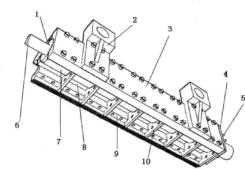
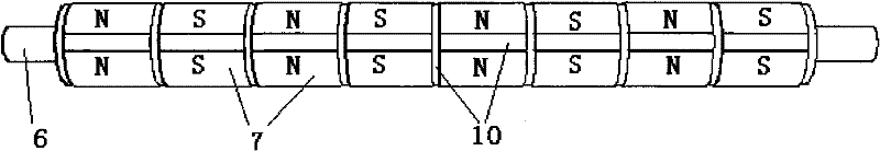
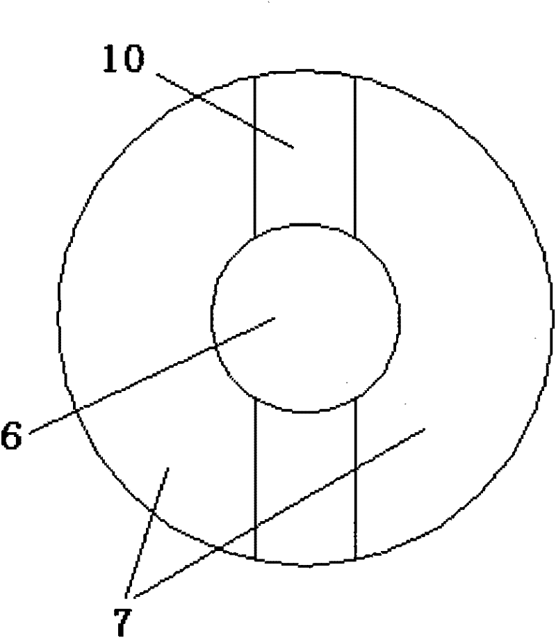
[0016] like Figure 1-3 As shown, the permanent magnet track brake has a permanent magnet shaft 6, and an even number of permanent magnets 7 are arranged on the outer ring of the permanent magnet shaft 6. The N poles and S poles of the magnets 7 are arranged at intervals with opposite polarities along the axial direction of the permanent magnet shaft 6 and alternately in sequence, and the permanent magnets 7 with the same polarity are arranged symmetrically at intervals along the central axis of the permanent magnet shaft 6 . A separator 10 is provided at the transverse and longitudinal gaps between the N pole and the S pole of the permanent magnet 7 . The separator 10 is made of a non-magnetic material and is in close contact with the permanent magnet 7 . The cross section of the spacer 10 is combined with the cross section of the permanent magnet 7 to be circular.

[0017] The bracket structure of the brake is composed of the upper top cover 3, the end covers 4 at both ends...


PUM


Abstract

The invention discloses a permanent magnet track brake. An outer ring of a permanent magnet axis is provided with permanent magnets of which the number is even; N and S poles of the permanent magnets are arranged alternately at intervals in turn along the axial direction of the permanent magnet axis in a way that the polarities are opposite; the permanent magnets with the same polarity are arranged symmetrically about the central axis of the permanent magnet axis at intervals; clapboards are arranged at transverse and longitudinal gaps of the N and S poles of the permanent magnets; pole shoesare arranged symmetrically on two sides and fixedly arranged close to the permanent magnets; the pole shoes correspond to S and N poles of the permanent magnets in the axial direction of the permanent magnet axis, the length of the pole shoes is consistent with that of the N and S poles, and the number of the pole shoes is the same as that of the permanent magnets; the clapboards are extended to gaps of adjacent pole shoes; eddy current braking and friction braking are realized according to different running speeds of railway vehicles, the abrasion of the pole shoes and rails is avoided, and the braking is realized and the service life of the pole shoes is prolonged simultaneously; the braking effect is improved; and the braking force is changed by controlling the rotating angle of the permanent magnet axis so as to realize safe and stable braking of the railway vehicles.

Description

technical field [0001] The invention relates to a magnetic track brake of a railway train vehicle, which realizes the braking or release of the railway train vehicle. Background technique [0002] The combined control of multiple braking methods in rail vehicles will greatly guarantee the driving safety of high-speed rail vehicles. At present, disc brakes are widely used in railway passenger vehicles, which reduces the degree of thermal damage to the wheel tread compared with tread brakes. However, as a sticking brake, the braking force produced by the disc brake is still limited by sticking conditions. Although the anti-skid device can be used to make the braking force approach the sticking limit, when it is necessary to further increase the train speed, it is necessary to modify and extend the braking distance in the technical specification to meet the needs of the vehicle speed increase. Therefore, in the development of quasi-high-speed, high-speed railway And new urban...

Claims


Application Information

Patent Timeline
Patent Type & Authority Patents(China)
IPC IPC(8): B61H7/00H02K49/04
Inventor 姚明何仁张晓娜
Owner JIANGSU UNIV
Why Eureka
Try Eureka