
Double-cylinder hydraulic grooving machine

A grooving machine and hydraulic technology, which is applied to earth moving machines/shovels, water conservancy projects, artificial islands, etc., can solve the problems of high maintenance cost, slow grooving speed, low efficiency, etc., and achieves strong power reliability, Simple structure and accurate positioning

Inactive Publication Date: 2012-07-04
NANTONG HUAZHENGLONG STEEL MFG
View PDF0 Cites 0 Cited by
  • Summary
  • Abstract
  • Description
  • Claims
  • Application Information

AI Technical Summary

Problems solved by technology

The bucket type grooving machine cuts the soil with its bucket teeth, stores the cut soil residue in the bucket body, transports it out of the ground from the trench, opens the bucket to pour out the soil residue, and then returns to the excavation position, so reciprocating work, power consumption Large and expensive; the impact type groove forming machine uses the drill bit to impact and break the foundation soil, and the soil slag is carried out of the groove by means of mud circulation. , rotary drilling into grooves, this way equipment maintenance cost is high
From the above analysis, it can be seen that the efficiency of the existing underground diaphragm wall groove forming machine is low, and the cost of construction equipment is high

Method used


Image

  • Double-cylinder hydraulic grooving machine
  • Double-cylinder hydraulic grooving machine

Examples


specific Embodiment

[0013] Accompanying drawing is a kind of specific embodiment of the present invention, advances by following several below:

[0014] 1. Deviation correction system

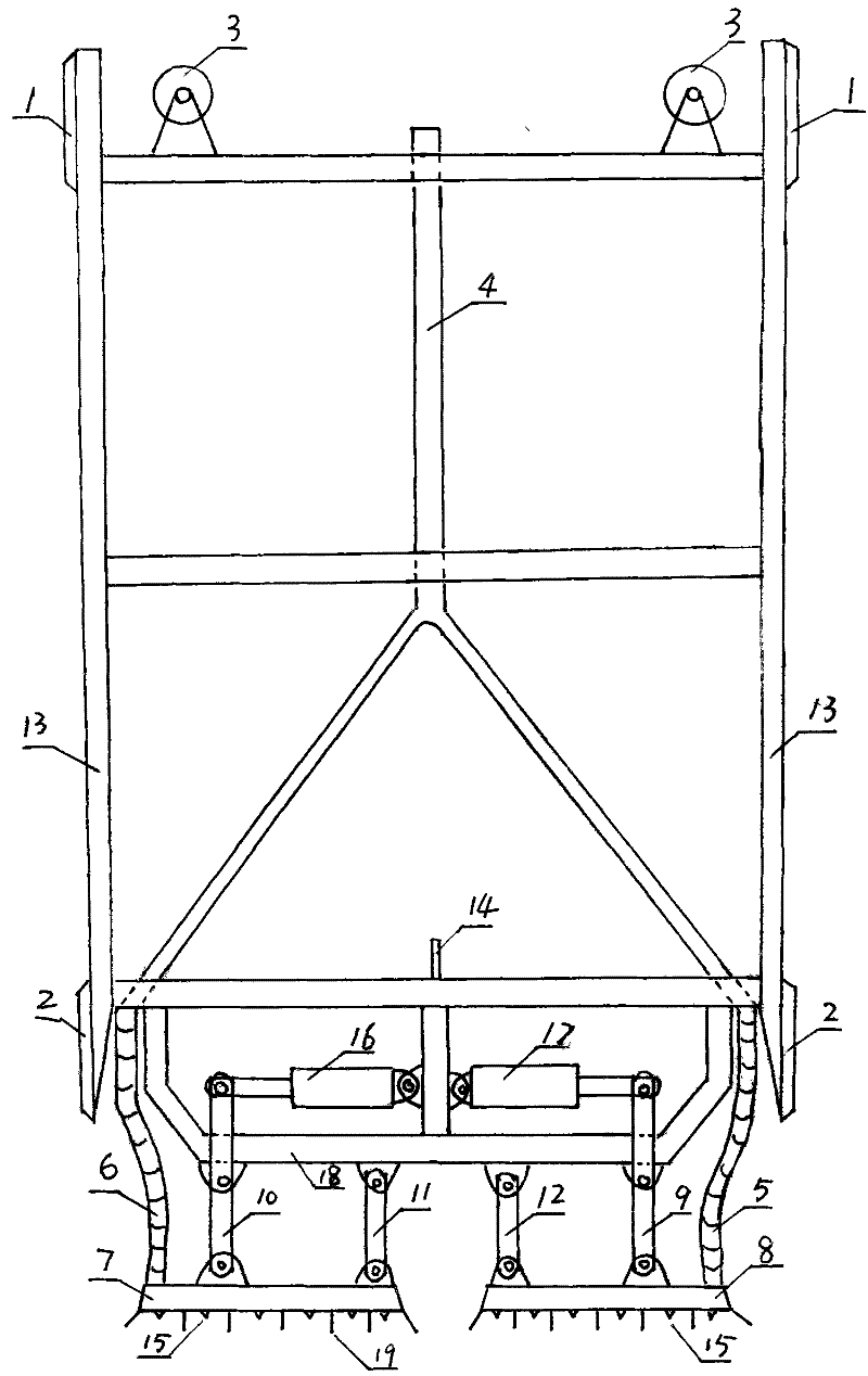
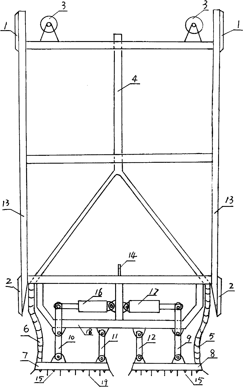
[0015] The deviation correction system is composed of two upper deviation correction plates 1, two lower deviation correction plates 2, an inclinometer 14 at the middle position, and two groups of arms on the frame. At the beginning of grooving, because the grooving machine is partly on the ground, its vertical guidance is completed by two groups of arms on the frame. There are two hydraulic rectifying plates on the left and right sides of the machine, which can be adjusted to the verticality of the machine.

[0016] 2. Slurry supply system

[0017] The slurry supply system is supplied by a high-pressure mud pump. The slurry is divided into two branches after passing through the water inlet pipe. One enters the tool holder A through the water inlet hose A, and the slurry is injected from several water nozzles on...


PUM


Abstract

The invention discloses a double-cylinder hydraulic grooving machine, comprising two upper derivation correcting plates, a left lower derivation correcting plate and a right lower derivation correcting plate, two lifting pulley blocks, a inclinometer in a middle position, a water inlet pipe, a water inlet rubber pipe A and a water inlet rubber pipe B. The grooving machine is characterized in thata left hydraulic cylinder A is hinged with the upper end of a left drive rocker A, the lower end thereof is in pin joint on a left knife rest A, and the middle part thereof is in pin joint on a beam;a right hydraulic cylinder B is hinged with the upper end of a right drive rocker B, the lower end thereof is in pin joint on a right knife rest B, and the middle part thereof is in pin joint on the beam; the upper end of a left driven rocker A is in pin joint on the beam, and the lower end thereof is in pin joint on the left knife rest A; the upper end of the right driven rocker B is in pin joint on the beam, and the lower end thereof is in pin joint on the right knife rest B; and a left water inlet rubber pipe A is connected on the left knife rest A, a right water inlet rubber pipe B is connected on the right knife rest B, and the flooding water is ejected by a water spray nozzle.

Description

1. Technical field [0001] The invention relates to a groove forming machine, in particular to a double-cylinder hydraulic groove forming machine for an underground continuous wall. 2. Background technology [0002] At present, the grooving machines used in the construction of underground diaphragm walls can be roughly divided into three types according to their grooving mechanism: bucket type, impact type and rotary type. The bucket type grooving machine cuts the soil with its bucket teeth, stores the cut soil residue in the bucket body, transports it out of the ground from the trench, opens the bucket to pour out the soil residue, and then returns to the excavation position, so reciprocating work, power consumption Large and expensive; the impact type groove forming machine uses the drill bit to impact and break the foundation soil, and the soil slag is carried out of the groove by means of mud circulation. , Rotary drilling into grooves, this way equipment maintenance cos...

Claims


Application Information

Patent Timeline
Patent Type & Authority Patents(China)
IPC IPC(8): E02F5/02E02F5/14E02D29/02
Inventor 张杰
Owner NANTONG HUAZHENGLONG STEEL MFG
Learn More