Silicon solar battery

A silicon solar cell and silicon substrate technology, applied in circuits, photovoltaic power generation, electrical components, etc., can solve problems such as increasing the effective light surface, and achieve the effect of increasing the power generation per unit area, increasing the effective light surface, and reducing the shading area.

Inactive Publication Date: 2010-05-19
SUN EARTH SOLAR POWER
View PDF0 Cites 28 Cited by
  • Summary
  • Abstract
  • Description
  • Claims
  • Application Information

AI Technical Summary

Problems solved by technology

But even if the busbars are made thinner, they still have a certain width. The area of ​​the busbars of the current solar cells is at least 3.5% of the total area, so this silicon solar cell cannot really achieve effective growth. Requirements for Large Effective Lighting Area

Method used


Image

  • Silicon solar battery
  • Silicon solar battery
  • Silicon solar battery

Examples


Embodiment Construction

[0016] The present invention will be further described in detail below in conjunction with the accompanying drawings and embodiments.

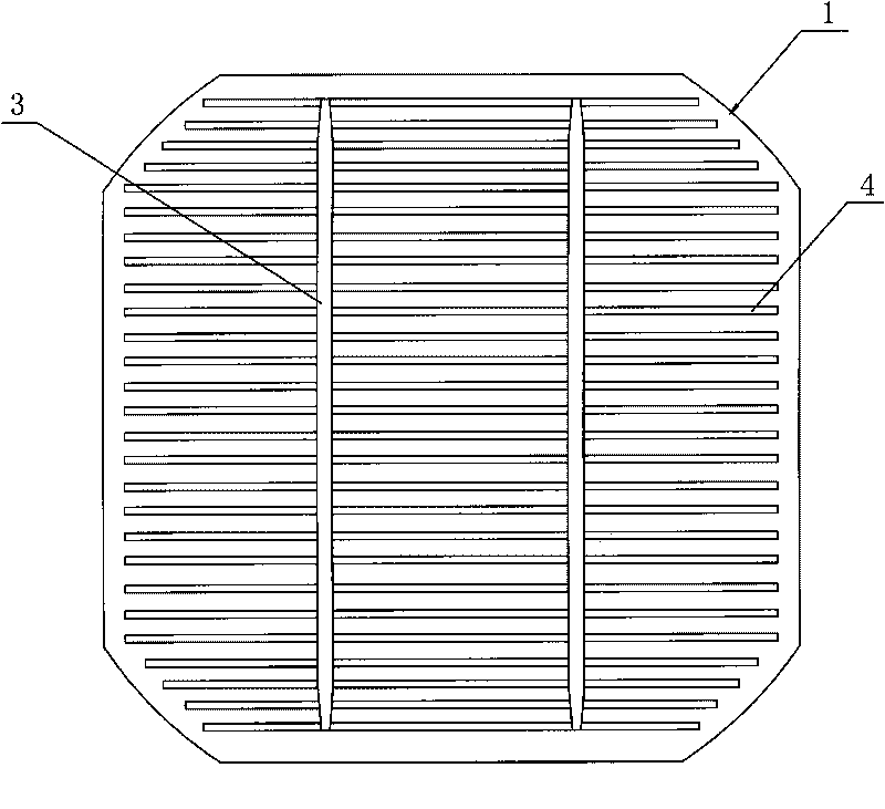
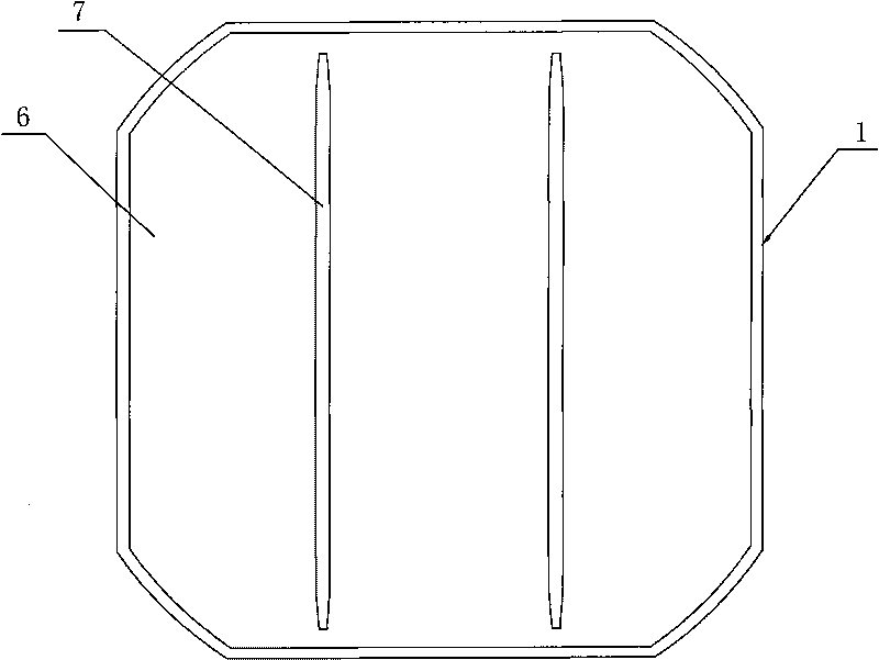
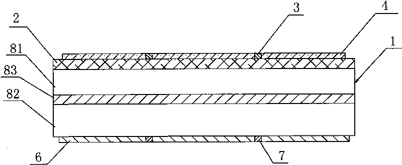
[0017] Such as Figure 2a , Figure 2b with Figure 2c As shown, a silicon solar cell includes a silicon substrate 11. The silicon substrate 11 can be selected according to the actual situation. For example, a silicon substrate with a resistivity of 0.6-2 ohms and a thickness of 0.2 mm is selected. 11 is doped with impurities, such as boron, phosphorus, etc. When boron atoms are doped, there will be a hole in the silicon substrate 11, forming a p-type semiconductor 12. Similarly, after doping phosphorus atoms, silicon substrate 11 will be There will be an electron to form an n-type semiconductor 13. When the p-type semiconductor 12 and n-type semiconductor 13 are combined, a potential difference is formed in the interface region between the two semiconductors, that is, a pn junction 14. A layer of silicon nitride film 15 is deposited on the...


PUM

PropertyMeasurementUnit
thicknessaaaaaaaaaa

Abstract

The invention discloses a silicon solar battery which comprises a silicon substrate, wherein a silicon nitride film is deposited on the front surface of the silicon substrate; a group of auxiliary grid lines are arranged on the silicon nitride film; an aluminum-back surface field (Al-BSF) made of aluminum slurry is coated on the back surface of the silicon substrate; a main grid line is arranged on the Al-BSF; a plurality of conducting through holes which penetrate through the silicon substrate are arranged on the silicon substrate; conducting slurry is filled in the conducting through holes; the auxiliary grid lines and the main grid line are respectively connected with two ends of the conducting slurry; and an insulation tank for isolating the Al-BSF from the main grid line is arranged at the periphery of the main grid line. The invention has the advantages that by arranging the main grid line on the back surface of the silicon substrate, arranging the conducting through holes on the silicon substrate and filling the conducting slurry into the conducting through holes, each auxiliary grid line is mutually conducted with the main grid line through the conducting slurry, and the current generated by the battery under the condition of illumination passes through the auxiliary grid lines and then passes through the conducting slurry to be converged onto the main grid line to be derived. In the battery with the structure, as the main grid line for converging current is arranged on the back surface of the silicon substrate, the effective illumination surface of the front surface of the battery is increased.

Description

technical field [0001] The invention relates to a battery, in particular to a silicon solar battery. Background technique [0002] With the increasing tension of global energy sources, solar energy has been widely valued by countries all over the world due to its unique advantages such as no pollution and large market space. There are many ways to utilize solar energy, including light-to-electricity conversion, light-to-heat conversion, and so on. Solar cells are the most typical example of light-to-electricity conversion, which are made using the photovoltaic principle of semiconductor materials. Solar cells can be divided into various types according to different types of semiconductor photoelectric conversion materials, among which silicon solar cells are the most common. [0003] At present, the more mature silicon solar cells commonly seen on the market such as Figure 1a , Figure 1b with Figure 1c As shown, the silicon solar cell includes a silicon substrate 1, a...

Claims


Application Information

Patent Timeline
Patent Type & Authority Applications(China)
IPC IPC(8): H01L31/05H01L31/0224
CPCY02E10/50
Inventor 肖剑峰费宏斌黄志林周体
Owner SUN EARTH SOLAR POWER
Why Eureka
Try Eureka